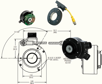
Couplings mechanically and electrically isolate the encoder from the motor. This separation helps avoid encoder signal errors such as miscounts or extra counts by reducing noise in the encoder. In addition, electrical isolation prevents damage caused by current from the motor.
Couplings also allow the encoder to compensate for shaft misalignment. Cutouts on the coupling allow flex to occur in the coupling rather than in the motor shaft. The runout from the shaft is absorbed by the coupling to prevent physical damage to the encoder.
Product Quicklinks
Call us at 800.873.8731
{{#if customLayout}}
{{html customLayout}}
{{else}}
{{#each items}}
{{#if products.results.length}}
{{products.title}}
{{/if}}
{{#if (or categories.results.length content.results.length queries.results.length)}}
{{#each products.results}}
{{/each}}
{{#if queries.results.length}}
{{queries.title}}
{{/if}}
-
{{#each queries.results}}
- {{query}} {{/each}}
-
{{#each productSuggestedQueries.results}}
- {{query}} {{/each}}
-
{{#each contentSuggestedQueries.results}}
- {{query}} {{/each}}
-
{{#each categories.results}}
- {{html title}} {{/each}}
-
{{#each content.results}}
- {{html title}} {{/each}}
{{#if (eq title "Search within results")}}
Search Within Results
{{#if tooltip}}
{{else}}
{{title}}
{{#if tooltip}}
{{/if}}
{{#unless collapsed}}
{{#if searchable}}
{{/if}}
{{#if (eq type "checkbox")}}
{{/unless}}
{{#if (myEq attributes.type "Product")}}
{{#if (myEq attributes.is_family "No")}}

{{#if attributes.list_price}} {{#if attributes.leadtime}} Buy Now!
{{/if}} {{/if}} View Product Info
{{else}}

{{#if attributes.family_page_link}} View Series Info {{else}} More Info {{/if}}
{{/if}}
{{else if (myEq attributes.type "Content")}}
{{#if (myEq attributes.content_type "Page")}}
More Info
{{else if (myEq attributes.content_type "BlogPost")}}
More Info
{{else}}
UNKNOWN TYPE 2 (type:{{attributes.type}}, content_type:{{attributes.content_type}})
{{/if}}
{{else}}
UNKNOWN TYPE 1: (type:{{attributes.type}}, content_type:{{attributes.content_type}})
{{/if}}
{{#if attributes.family_id}}
{{attributes.family_id}}
{{/if}}
{{#if attributes.part_number}}
{{/if}}
{{#if (myEq attributes.consult_factory_price "1")}}
Consult Factory
{{else}}
{{#if (isNumber attributes.list_price)}}
{{currency attributes.list_price}} {{attributes.currency_code}}
{{/if}}
{{/if}}
{{attributes.description}}
{{#if (myEq attributes.consult_factory_leadtime "1")}}
Consult Factory
{{else}}
{{#if (isNumber attributes.leadtime)}}
{{isInt attributes.leadtime}} {{attributes.leadtime_period}}
{{/if}}
{{/if}}
{{#if attributes.data_sheet_link}}
Download Datasheet
{{/if}} {{#if attributes.installation_manual_link}} Download Installation Manual {{/if}}
{{/if}} {{#if attributes.installation_manual_link}} Download Installation Manual {{/if}}
{{#if attributes.list_price}} {{#if attributes.leadtime}} Buy Now!
{{/if}} {{/if}} View Product Info
{{#if attributes.family_id}}
{{attributes.family_id}}
{{else}}
{{/if}}
{{#if attributes.description}}
{{#if attributes.family_page_link}}
{{truncateWithMore attributes.description attributes.family_page_link}}
{{else}}
{{truncateWithMore attributes.description attributes.url_detail}}
{{/if}}
{{/if}}
{{#if attributes.data_sheet_link}}
Download Datasheet
{{/if}} {{#if attributes.installation_manual_link}} Download Installation Manual {{/if}}
{{/if}} {{#if attributes.installation_manual_link}} Download Installation Manual {{/if}}
{{#if attributes.family_page_link}} View Series Info {{else}} More Info {{/if}}
{{#if attributes.description}}
{{#if attributes.family_page_link}}
{{truncateWithMore attributes.description attributes.family_page_link}}
{{else}}
{{truncateWithMore attributes.description attributes.url_detail}}
{{/if}}
{{else if attributes.description_short}}
{{#if attributes.family_page_link}}
{{truncateWithMore attributes.description_short attributes.family_page_link}}
{{else}}
{{truncateWithMore attributes.description_short attributes.url_detail}}
{{/if}}
{{/if}}
{{#if attributes.data_sheet_link}}
Download Datasheet
{{/if}} {{#if attributes.installation_manual_link}} Download Installation Manual {{/if}}
{{/if}} {{#if attributes.installation_manual_link}} Download Installation Manual {{/if}}
More Info
{{#if strings.summary}}
{{strings.summary}}
{{/if}}
{{#if content.customHtml}}
{{html content.customHtml}}
 {{/if}}
{{searchResultsFor}}