How to Calculate Encoder Resolution

Encoder resolution is the number of pulses per revolution (PPR) or bits output by the encoder during one 360 degree revolution of the encoder shaft or bore. If an encoder has insufficient resolution, it will not provide effective feedback to the controller and the system will not perform as required.

To calculate encoder resolution, for incremental encoders, the calculation will depend on your max RPM and encoder operating frequency. For absolute encoders, it will depend on the protocol baud rate and how often the system requires position information.

Free White Paper Resources:

The Right Feedback Option
Absolute vs Incremental Encoders
Encoder Mounting
Feedback Essentials White Paper  Encoders or Resolvers? How to Choose the Right Feedback Option Download Now
New Call-to-Action
Encoder Essentials  Encoder Mounting. Optimizing the Life and Performance of Rotary Encoders Download Now
     

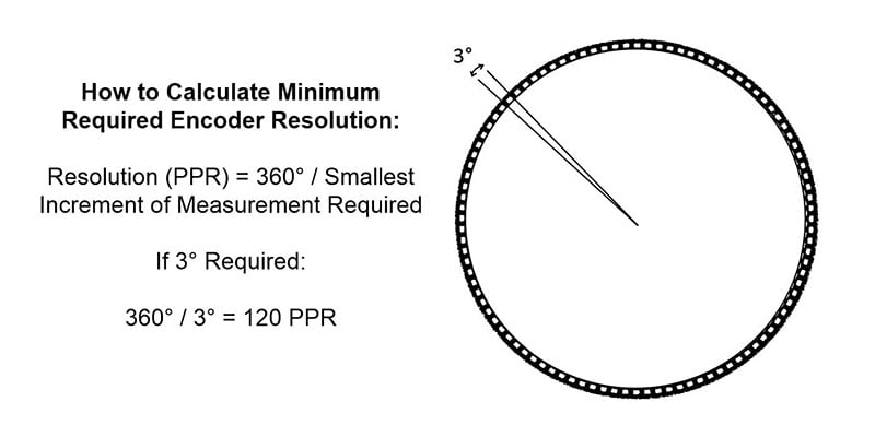
Determine Minimum Encoder Resolution Required

Specifying resolution starts with determining the smallest increment I that needs to be monitored for the application. For example, consider a rotary application that needs to measure to 3°. The number of points N we want to measure per revolution is given by:

N = 360 / I

In the example above, N = 360 / (3) = 120 pulses per revolution.

encoder-resolution-ppr-calculation

Incremental Encoder Resolution (PPR) Calculation

For incremental encoders, the encoder electronics have a maximum frequency response, which limits how rapidly it can generate output pulses. Combined with the RPM of the application, the frequency response places a practical upper bound on the resolution that can actually be achieved for a particular system and encoder.

Max encoder resolution = Operating Frequency x 60 / Max RPM

Exceeding this number will overwork the encoder’s processing capability, which will result in degraded signal output and cumulative error.

For example, if the encoder’s operating frequency is 125kHz and the maximum shaft speed is 1,000 RPM, the encoder ppr calculation for the maximum resolution the encoder supports is 7,500 pulses per revolution (PPR).

If your encoders standard resolution doesn’t meet your application needs, there is another alternative based on how the signal is decoded through the users drive, PLC or Controller. Assuming the usage of quadrature encoders with bidirectional output (A and B channels), triggering from the rising and falling edges of the A channel and the B channel will generate four times as many pulses, or 4X encoding.

Learn more about quadrature encoders and encoding to achieve higher resolutions here

Absolute Encoder Resolution (Bits) Calculation

Unlike incremental encoders that are a push only system that output a continuous stream of pulses whenever the shaft is turned, absolute encoders are a call and response system that output a bit or unique word that relates to discrete position only when they are interrogated by the controlling device. Therefore, absolute encoders are not limited by frequency response in relation to total pulses but by the amount of data communication required over a specific sample period, or baud rate.

To determine number of discrete positions required (N), first determine the smallest incremental of measurement (I) required within 360 degree rotation:

N = 360 / I

For example, if you require measuring down to 0.01 degrees, the resulting calculation would be N = 360 / (0.03) = 12,000 discrete positions.

Next, convert the number of discrete positions required to the next highest bit count. The code discs of absolute encoders are patterned to generate a unique digital word for a specific number of angular or linear positions of the load. As a result, the resolution is measured in terms of bits N, with the encoder measuring 2N positions per revolution. A 14-bit encoder, for example, can measure 16,384 discrete positions per one revolution of 360°, which would satisfy the above example.

Example Encoder Resolution (Bits) Discrete Positions
12 Bit Encoder 4,096
13 Bit Encoder 8,192
14 Bit Encoder 16,384
15 Bit Encoder 32,768
16 Bit Encoder 65,536
17 Bit Encoder 131,072
18 Bit Encoder 262,144
19 Bit Encoder 524,288
20 Bit Encoder 1,048,576
21 Bit Encoder 2,097,152
22 Bit Encoder 4,194,304

How to Determine Encoder Baud Rate

Baud rate is unique for each encoder communication protocol and varies by cable length. Generally, baud rates decrease as cable length increases. For example, for the SSI encoder interface protocol, the recommended data transfer rate by cable length is:

Cable Length vs. Data Rate for SSI Encoders
Cable Length Data Rate
50 m 400 kHz
100 m 300 kHz
200 m 200 kHz
400 m 100 kHz

In the case of SSI, a long cable run and a high clock frequency can disturb the data signal due to propagation delay of the signals over copper wires and it is necessary to reduce the clock frequency or the cable length for the system to work. Some protocols, such as BiSS allow for a delay compensation to improved performance over longer cable runs.

Learn more about SSI Encoders Here

Learn more about BiSS Encoders Here

View Dynapar’s Absolute Encoders by Resolution:

Dalsen-Ferbert
Written By: Dalsen Ferbert​
Midwest Territory Manager, Mechanical Engineer

Find The Right Feedback Solution for Your Application

Use our selection tool to narrow down your search

Step 1: Select Feedback Type (Learn How to Choose)

Absolute Encoder

Incremental Encoders