
How to Mount and Install a Resolver
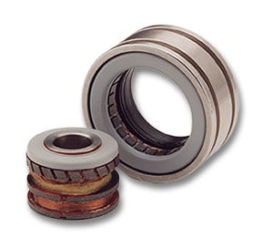
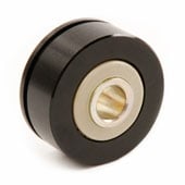
Frameless resolvers provide OEMs and machine builders with important design flexibility. Housed resolvers are built with specific mounting surfaces and hole patterns. Frameless resolvers are supplied as separate rotor and stator assemblies, which enables them to be built directly into the equipment.
Feedback Essentials White Paper
Encoders or Resolvers? How to Choose the Right Feedback Option

This supports smaller form factors, lighter weights, and innovative designs. Frameless resolvers require a certain amount of expertise to mount and install, however. Here, we review the requirements and discuss common error sources and pitfalls in applying the technology.
A resolver is a type of transformer that measures angle based on electromagnetic interaction between the primary winding (rotor) and secondary windings (stator). As a result, the performance depends upon the proper alignment of rotor and stator with respect to each other. Housed resolvers are pre-aligned at the factory. To obtain accurate results from a frameless resolver, the user needs to build mounting elements into the equipment and install the rotor and stator to meet alignment tolerances.
How to Design a Resolver Mounting Mechanism
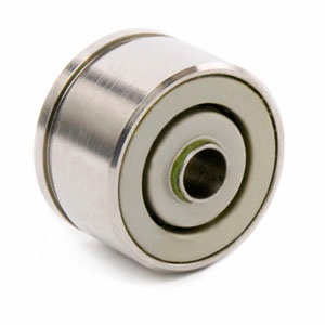
 In a frameless resolver, the rotor is directly mounted to the shaft of the motor or load, and the stator is directly mounted to the housing. The process starts with designing and machining mounting surfaces and bearings onto the equipment. To ensure that the resolver performs to specifications, the mounting surfaces must meet the following tolerances:
- Axial misalignment or variation in the mounting dimensions between the resolver rotor and the resolver stator housing mounting surfaces should not exceed 0.015 inches.
- Eccentricities between the rotor and stator mounting surfaces should not exceed 0.003 inch.
- Mounting shoulders should be perpendicular to the bores and shafts of the structure to within 0.0005 inch.
- The fit between the bore and the maximum stator housing OD, and between the shaft and the rotor ID should be from 0.0002 to 0.001 inch loose. This will ensure that there is no line-to-line fit or interference fit.
- Stator housing and shaft should be made of materials with coefficients of thermal expansion that are similar to those of the resolver rotor and stator.
The above guidelines have been developed for a typical application. Depending on the unit size, air gap clearance, accuracy, and other electrical requirements, tolerances may need to be loosened or tightened to ensure desired performance.
How to Install a Resolver
Once the mounting elements are machine and in place, the rotor and stator need to be installed. Because the resolver is based on the electromagnetic interaction between rotor and stator, proper electrical alignment is essential to accurate position reporting. Installation of a resolver is for a position for commutation application is normally a four-step process.
- Firmly secure the resolver rotor to the motor shaft, aligning the electrical zero mark so that the lead of the resolver stator will exit in the approximate desired position when marks coincide. Next, attach the resolver stator to the motor end-bell with a temporary snug fit.
- Align the resolver zero position with a motor pole for commutation. This can be accomplished several different ways.
- Apply a DC current across two motor phases, which “locks” the motor shaft at a pole position. Connect the resolver to an angle position indicator, and rotate the resolver stator until the indicated angle is zero degrees. Firmly secure the resolver stator in this position.
- Mechanically drive the motor with a second motor. While the two are spinning, view the back EMF of the motor being configured on an oscilloscope. Simultaneously, view the resolver signals on the scope. Rotate the resolver stator until the zero crossing of the back EMF coincides with the resolver zero position signal. Firmly secure the stator in this position.
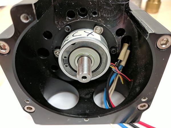
The above image shows a resolver mounted to a motor with the rotor mounted to the motor shaft and stator securely fastened in position.
Symptoms of Improper Resolver Installation and Alignment
If the tolerances above are exceeded as a result of buildup of system tolerances or defective system hardware, the electrical characteristics of the resolver will change. The magnitude of these changes depends on the resolver size, air gap clearance, and whether it is a single speed or multispeed resolver. The performance of the unit will generally be affected as follows:
Symptoms of axial offset:
- Output voltage will decrease
- Electrical error will increase (and accuracy decrease) only slightly
- Null voltage will change in magnitude
- Phase shift will increase
- Input current and power will increase
Symptoms of radial offset
- Electrical error will increase (and accuracy decrease) proportionally
- Null voltage will change in magnitude
- Output voltage will show small change
- Phase shift will show small change
- Input current and power will show small change
Symptoms of resolver rotor or housing tilt
If the rotor or housing tilt is slight (about 0.0001 or 0.0002 inches with respect to each other), very little change will occur in any parameter. Tilts greater than this must be avoided in units with small air gap clearances to prevent contact between the rotor assembly and the stator assembly. In addition, increased tilt between rotor and stator will increase position and velocity error.
Additional Resolver Resources
Learn more about resolver technology here
Learn how to specify resolver speed and accuracy here
Learn more about resolver output and voltage here
Download our white paper on the key differences between encoders and resolvers here
Download our white paper on how to specify the best resolver for your application here
Dynapar's Most Popular Resolvers
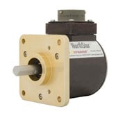
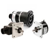
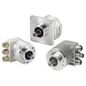
Dynapar offers frameless resolver and housed resolver options. Frameless resolvers with rotor and stator assemblies that can be housed in servo motors, direct drive motors, rotary platforms and more to provide motion feedback. Housed resolvers provide reliable feedback in a sealed package with various IP rated models. See our most popular resolver models:
{{#if customLayout}}
{{html customLayout}}
{{else}}
{{#each items}}
{{#if products.results.length}}
{{products.title}}
{{/if}}
{{#if (or categories.results.length content.results.length queries.results.length)}}
{{#each products.results}}
{{/each}}
{{#if queries.results.length}}
{{queries.title}}
{{/if}}
-
{{#each queries.results}}
- {{query}} {{/each}}
-
{{#each productSuggestedQueries.results}}
- {{query}} {{/each}}
-
{{#each contentSuggestedQueries.results}}
- {{query}} {{/each}}
-
{{#each categories.results}}
- {{html title}} {{/each}}
-
{{#each content.results}}
- {{html title}} {{/each}}
{{#if (eq title "Search within results")}}
Search Within Results
{{#if tooltip}}
{{else}}
{{title}}
{{#if tooltip}}
{{/if}}
{{#unless collapsed}}
{{#if searchable}}
{{/if}}
{{#if (eq type "checkbox")}}
{{/unless}}
{{#if (myEq attributes.type "Product")}}
{{#if (myEq attributes.is_family "No")}}

{{#if attributes.list_price}} {{#if attributes.leadtime}} Buy Now!
{{/if}} {{/if}} View Product Info
{{else}}

{{#if attributes.family_page_link}} View Series Info {{else}} More Info {{/if}}
{{/if}}
{{else if (myEq attributes.type "Content")}}
{{#if (myEq attributes.content_type "Page")}}
More Info
{{else if (myEq attributes.content_type "BlogPost")}}
More Info
{{else}}
UNKNOWN TYPE 2 (type:{{attributes.type}}, content_type:{{attributes.content_type}})
{{/if}}
{{else}}
UNKNOWN TYPE 1: (type:{{attributes.type}}, content_type:{{attributes.content_type}})
{{/if}}
{{#if attributes.family_id}}
{{attributes.family_id}}
{{/if}}
{{#if attributes.part_number}}
{{/if}}
{{#if (myEq attributes.consult_factory_price "1")}}
Consult Factory
{{else}}
{{#if (isNumber attributes.list_price)}}
{{currency attributes.list_price}} {{attributes.currency_code}}
{{/if}}
{{/if}}
{{attributes.description}}
{{#if (myEq attributes.consult_factory_leadtime "1")}}
Consult Factory
{{else}}
{{#if (isNumber attributes.leadtime)}}
{{isInt attributes.leadtime}} {{attributes.leadtime_period}}
{{/if}}
{{/if}}
{{#if attributes.data_sheet_link}}
Download Datasheet
{{/if}} {{#if attributes.installation_manual_link}} Download Installation Manual {{/if}}
{{/if}} {{#if attributes.installation_manual_link}} Download Installation Manual {{/if}}
{{#if attributes.list_price}} {{#if attributes.leadtime}} Buy Now!
{{/if}} {{/if}} View Product Info
{{#if attributes.family_id}}
{{attributes.family_id}}
{{else}}
{{/if}}
{{#if attributes.description}}
{{#if attributes.family_page_link}}
{{truncateWithMore attributes.description attributes.family_page_link}}
{{else}}
{{truncateWithMore attributes.description attributes.url_detail}}
{{/if}}
{{/if}}
{{#if attributes.data_sheet_link}}
Download Datasheet
{{/if}} {{#if attributes.installation_manual_link}} Download Installation Manual {{/if}}
{{/if}} {{#if attributes.installation_manual_link}} Download Installation Manual {{/if}}
{{#if attributes.family_page_link}} View Series Info {{else}} More Info {{/if}}
{{#if attributes.description}}
{{#if attributes.family_page_link}}
{{truncateWithMore attributes.description attributes.family_page_link}}
{{else}}
{{truncateWithMore attributes.description attributes.url_detail}}
{{/if}}
{{else if attributes.description_short}}
{{#if attributes.family_page_link}}
{{truncateWithMore attributes.description_short attributes.family_page_link}}
{{else}}
{{truncateWithMore attributes.description_short attributes.url_detail}}
{{/if}}
{{/if}}
{{#if attributes.data_sheet_link}}
Download Datasheet
{{/if}} {{#if attributes.installation_manual_link}} Download Installation Manual {{/if}}
{{/if}} {{#if attributes.installation_manual_link}} Download Installation Manual {{/if}}
More Info
{{#if strings.summary}}
{{strings.summary}}
{{/if}}
{{#if content.customHtml}}
{{html content.customHtml}}
{{/if}}
{{#if (myEq content.heading "Incremental Encoders")}}
 {{else if (myEq content.heading "Absolute Encoders")}}
 {{/if}}
{{else if (myEq content.heading "Absolute Encoders")}}
{{/if}}
{{searchResultsFor}}