Free White Paper Resources:
❮
Position Problems
Encoder Mounting
IP Ratings


❯
Indirect by Monitoring Motor Shaft with an Encoder
The indirect measurement method involves monitoring the shaft of the motor driving the conveyor belt. The encoder should be mounted directly to the motor shaft. It will output either a pulse stream (for an incremental encoder) or a digital word (for an absolute encoder) that corresponds to the displacement of the motor shaft.
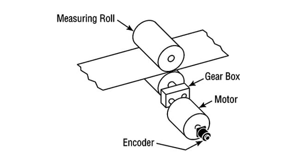 To convert from encoder output, it is necessary to physically measure the amount of travel introduced by one rotation of the motor. For a constant travel L, the drive can calculate speed s in feet per second by:

where fp is pulse frequency in hertz.
The drawback to this approach is that it does not consider mechanical slop that may be introduced by the coupling, gearbox, belt slip, etc. This also brings up an important point: the mechanical performance of the conveyor belt and the speed resolution of the motor are the limiting factors in maintaining consistent speed with a conveyor belt. All an encoder can do is report. The resolution needs to be high enough that it the encoder can accurately report the change in position that gets converted to speed. Specifying an encoder with resolution above that will not improve system performance and may even lead to an erroneous reading.
Indirect Measurement of Roller Shaft with an Encoder
Depending on access to the motor, it might be easier to mount the encoder on the roller shaft.
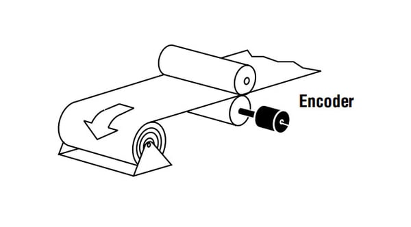
In this case, the drive converts the encoder output to linear speed s in feet per second as follows:

where fp is pulse frequency in hertz, R is resolution in pulses per revolution. Linear speed s is given by:

where D is diameter of the roller in inches.
Although more accurate than a motor-mounted encoder, this approach still suffers from mechanical error introduced by belt slip, etc.
Direct Measurement Using an Encoder Measuring Wheel
The third way to monitor conveyor speed is to attach an encoder to an encoder measuring wheel that rides on the surface of the belt or one of the rollers if the belt itself is crowded with product. Typically, these wheels are 1 foot in circumference, which makes an easy conversion from RPM to linear speed in feet per minute.
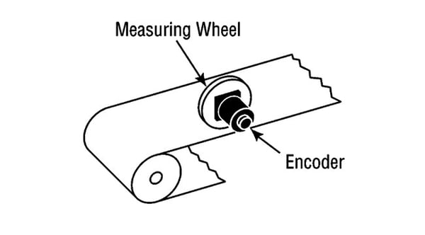
It is important to remember that a follower wheel is a mechanical assembly and can degrade accuracy. Error sources include misalignment and slippage between the wheels and the surface being measured. Applying preload helps prevent that slip but increases bearing wear. Finally, the follower wheel itself can wear, particularly in the case of misalignment. To address this problem, some encoder measuring wheels feature dual O-rings on the circumference that can be replaced when necessary, extending the lifetime of the wheel itself. And remember, the follower wheel, not the performance of the encoder, is the limiting error source.
 {{else if (myEq content.heading "Absolute Encoders")}}
 {{/if}}