
Encoder Wiring Best Practices
Obtaining a good quality signal is essential to effective encoder feedback. Selecting the right cable for your application is critical but proper encoder wiring is key to building a long-lasting, reliable machine. Following encoder wiring best practices can help avoid common pitfalls and will lead to a system that operates as expected.

Encoder wiring best practices:
- Follow the encoder wiring scheme or pinout designated on the encoder datasheet
- Run cabling in conduits, away from power cables.
- Shield cables and or individual wires to protect from EMI.
- Avoid ground loops. Ground cables on one side only.
- Adjust wiring for proper phasing in quadrature encoders.
Encoder Wiring Scheme
Encoder wiring schemes can be unique to each encoder and one should follow the diagram or pinout designated on the encoder datasheet. Multi-channel differential encoder wiring with commutation tracks can have up to 14 wires and miswiring can result in signal issues such as deformed pulses, low signal amplitude and shorted connections.
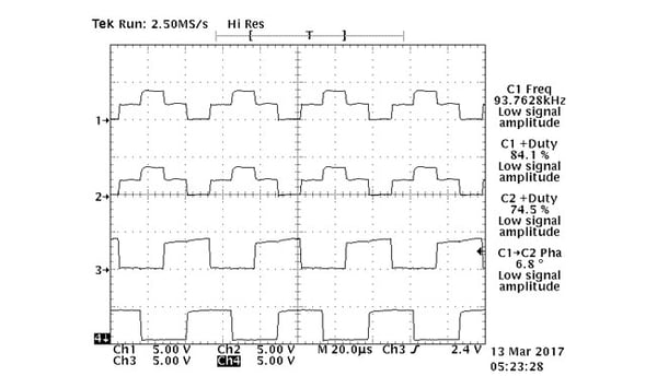 Example of shorted A and B wires (1 and 2 in diagram) resulting in distorted pulse shape on both channels
Reducing Signal Noise
An optical encoder cannot act as a feedback device without wiring. The problem is that wires act as antennas, which enables them to pick up radiated signals from nearby sources; the longer the encoder wire, the more pronounced the effect. In environments with high electromagnetic interference (EMI), applying techniques to block noise should be the first consideration. Encoder cabling should be run in conduits, preferably separate from other wires. If this is not possible, they should be run only with other low-power DC cables. Signal wires should be at least 1 foot away from power cables.

Shielding is important. At minimum, the cable should be protected either by a foil jacket with a drain wire or by a braided-wire shield that is grounded. For very sensitive applications or high-EMI environments, foil jacketed wires in combination with an overall braided-wire shield around the cable should be used.
Grounding Encoder Wires
It’s important to apply proper grounding techniques. Both the encoder case and the encoder cable/connector should not be grounded. Dynapar encoders usually have provisions for a case ground connection through the connector/cable if a ground cannot be secured to the mounting bracket/machine ground.
Take care to ground your cable at one end only. Grounding at multiple points can create ground loops, which can lead to AC-induced noise. The best approach is to ground it through the connector, ideally on the drive side, assuming the drive is grounded.
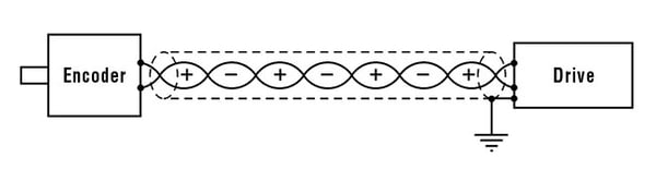
In industrial environments, high current fluxes are created by motors, remote control switches and magnetic fields. This can result in varying electrical potentials at different ground points. To avoid problems, ground the encoder cable shield, together with all other parts of the system requiring grounding, from a single point at the instrument end, as shown.
Preventing Motor Shaft Currents
Variable-frequency drives can induce currents in the shaft, rotor, and housing of the motor. This is a result of the high switching frequency of the VFDs. The currents pass through the bearings, which can damage the balls inside of the raceways.
It’s important to isolate the encoder from the shaft currents. This can be done using grounding brushes that directly contact the motor shaft. The shaft, in turn, connects to the motor frame so that any induced currents will go straight to the motor frame. That protects the bearings for both encoder and motor, alike.
Techniques for grounding bearings include:
- Isolated bearings
- Conductive grease to help spread the discharge bearings
- Insulated inserts for mounting hollow-shaft encoders, including isolation washers and nylon washers
Encoder Phase and Reversing Phasing
Quadrature or incremental encoders make it possible to determine the direction of rotation by maintaining a 90° phase lag between the signal from an A channel and a matching but physically offset B channel on the code disc. If the A channel pulse leads that of the B channel, the receiving device might interpret the difference as clockwise rotation, while a phase lag would indicate counter-clockwise movement.
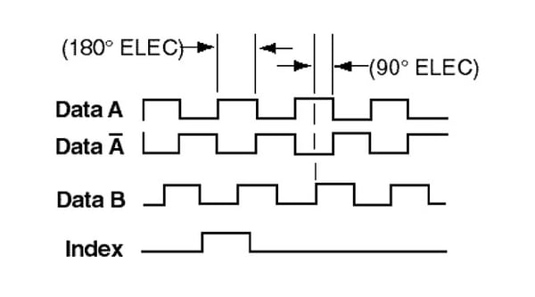
Example phase diagram of the HS35R hollow-shaft encoder. In this example, A leads B for clockwise shaft rotations when viewing the shaft clamp end of the encoder. A common issue with a hollow-shaft encoder is installing the encoder backward leading to reversed phasing.
Sometimes, particularly when one type of encoder is being swapped out for another, the phasing relationship may be the opposite of what is expected. This could create a significant problem in the equipment. Fortunately, correcting the situation is fairly simple:
- For a quadrature encoder, just reverse the wires for the A and the B channels
- For a differential encoder, swap the A and A’ wires but leave the B and B’ wires alone. That effectively swaps the phasing between A and B and at the same time A' and B'
Looking for a Custom Solution?
Tell us your requirements and our application engineers will help find the right solution today.
Contact Us →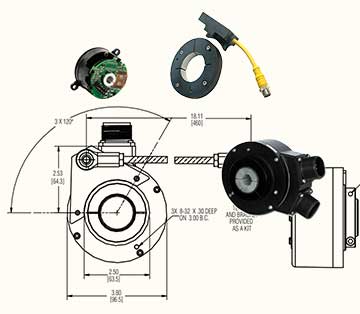
{{#if customLayout}}
{{html customLayout}}
{{else}}
{{#each items}}
{{#if products.results.length}}
{{products.title}}
{{/if}}
{{#if (or categories.results.length content.results.length queries.results.length)}}
{{#each products.results}}
{{/each}}
{{#if queries.results.length}}
{{queries.title}}
{{/if}}
-
{{#each queries.results}}
- {{query}} {{/each}}
-
{{#each productSuggestedQueries.results}}
- {{query}} {{/each}}
-
{{#each contentSuggestedQueries.results}}
- {{query}} {{/each}}
-
{{#each categories.results}}
- {{html title}} {{/each}}
-
{{#each content.results}}
- {{html title}} {{/each}}
{{#if (eq title "Search within results")}}
Search Within Results
{{#if tooltip}}
{{else}}
{{title}}
{{#if tooltip}}
{{/if}}
{{#unless collapsed}}
{{#if searchable}}
{{/if}}
{{#if (eq type "checkbox")}}
{{/unless}}
{{#if (myEq attributes.type "Product")}}
{{#if (myEq attributes.is_family "No")}}

{{#if attributes.list_price}} {{#if attributes.leadtime}} Buy Now!
{{/if}} {{/if}} View Product Info
{{else}}

{{#if attributes.family_page_link}} View Series Info {{else}} More Info {{/if}}
{{/if}}
{{else if (myEq attributes.type "Content")}}
{{#if (myEq attributes.content_type "Page")}}
More Info
{{else if (myEq attributes.content_type "BlogPost")}}
More Info
{{else}}
UNKNOWN TYPE 2 (type:{{attributes.type}}, content_type:{{attributes.content_type}})
{{/if}}
{{else}}
UNKNOWN TYPE 1: (type:{{attributes.type}}, content_type:{{attributes.content_type}})
{{/if}}
{{#if attributes.family_id}}
{{attributes.family_id}}
{{/if}}
{{#if attributes.part_number}}
{{/if}}
{{#if (myEq attributes.consult_factory_price "1")}}
Consult Factory
{{else}}
{{#if (isNumber attributes.list_price)}}
{{currency attributes.list_price}} {{attributes.currency_code}}
{{/if}}
{{/if}}
{{attributes.description}}
{{#if (myEq attributes.consult_factory_leadtime "1")}}
Consult Factory
{{else}}
{{#if (isNumber attributes.leadtime)}}
{{isInt attributes.leadtime}} {{attributes.leadtime_period}}
{{/if}}
{{/if}}
{{#if attributes.data_sheet_link}}
Download Datasheet
{{/if}} {{#if attributes.installation_manual_link}} Download Installation Manual {{/if}}
{{/if}} {{#if attributes.installation_manual_link}} Download Installation Manual {{/if}}
{{#if attributes.list_price}} {{#if attributes.leadtime}} Buy Now!
{{/if}} {{/if}} View Product Info
{{#if attributes.family_id}}
{{attributes.family_id}}
{{else}}
{{/if}}
{{#if attributes.description}}
{{#if attributes.family_page_link}}
{{truncateWithMore attributes.description attributes.family_page_link}}
{{else}}
{{truncateWithMore attributes.description attributes.url_detail}}
{{/if}}
{{/if}}
{{#if attributes.data_sheet_link}}
Download Datasheet
{{/if}} {{#if attributes.installation_manual_link}} Download Installation Manual {{/if}}
{{/if}} {{#if attributes.installation_manual_link}} Download Installation Manual {{/if}}
{{#if attributes.family_page_link}} View Series Info {{else}} More Info {{/if}}
{{#if attributes.description}}
{{#if attributes.family_page_link}}
{{truncateWithMore attributes.description attributes.family_page_link}}
{{else}}
{{truncateWithMore attributes.description attributes.url_detail}}
{{/if}}
{{else if attributes.description_short}}
{{#if attributes.family_page_link}}
{{truncateWithMore attributes.description_short attributes.family_page_link}}
{{else}}
{{truncateWithMore attributes.description_short attributes.url_detail}}
{{/if}}
{{/if}}
{{#if attributes.data_sheet_link}}
Download Datasheet
{{/if}} {{#if attributes.installation_manual_link}} Download Installation Manual {{/if}}
{{/if}} {{#if attributes.installation_manual_link}} Download Installation Manual {{/if}}
More Info
{{#if strings.summary}}
{{strings.summary}}
{{/if}}
{{#if content.customHtml}}
{{html content.customHtml}}
{{/if}}
{{#if (myEq content.heading "Incremental Encoders")}}
 {{else if (myEq content.heading "Absolute Encoders")}}
 {{/if}}
{{else if (myEq content.heading "Absolute Encoders")}}
{{/if}}
{{searchResultsFor}}