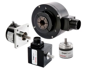
Quadrature Encoder Overview
When industrial motion applications require detection of direction in addition to speed, quadrature encoders provide a reliable solution.
What is a quadrature encoder?
A quadrature encoder is an incremental encoder with two out-of-phase output channels used in many general automation applications where sensing the direction of movement is required. Each channel provides a specific number of equally spaced pulses per revolution (PPR), and the direction of motion is detected by the phase relationship of one channel leading or trailing the other channel.Speak with a Dynapar expert to learn more about quadrature encoders.
Free White Paper Resources:
❮
Encoder Mounting
Upgrading Your Feedback System
IP Rating


❯
How does a Quadrature Encoder work?
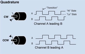
Inside a quadrature encoder, the code disk contains two tracks, usually denoted Channel A and Channel B. These tracks or channels are coded ninety electrical degrees out of phase, as indicated in the image below, and this is the key design element that will provide the quadrature encoder its functionality. In applications requiring direction sensing, a controller can determine the direction of movement based on the phase relationship between Channels A and B. As illustrated in the example optical encoder figure below, when the encoder is rotating in a clockwise direction, its signal will show Channel A leading Channel B, and the reverse will happen when the quadrature encoder rotates counterclockwise.
Apart from direction, position can also be monitored with a quadrature encoder by producing another signal known as the “marker”, “index,” or “Z channel.” This Z signal, produced once per complete revolution of the quadrature encoder, is often used to locate a specific position during a 360° revolution.
How and when to use a Quadrature Encoder
Quadrature encoders are used in bidirectional position sensing and length measuring applications. However, in some unidirectional start-stop applications, it is important to have bidirectional information (Channel A & B) even if the reverse rotation of the shaft is not anticipated. An error in count could occur with a single-channel encoder due to machine vibration inherent in the system. For example, an error in count may occur with a single-channel encoder in a start/stop application if it mechanically stops rotating when the output waveform is in transition. As subsequent mechanical shaft vibration forces the output back and forth across the edge, the counter will up-count with each transition, even though the system is virtually stopped. By utilizing a quadrature encoder, the counter monitors the transition in its relationship to the state of the opposite channel and can generate reliable position information.
Our Most Popular Quadrature Encoders
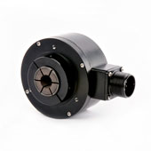
HS35R Hollow-shaft Quadrature Encoder
Reliable Hollow-Shaft Encoder Offers Encoder Performance for Heavy Duty Applications
Customize & Buy Now
View Key Product Features
- Up to 5000 PPR
- Optical Sensing
- Up to IP67
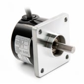
HA25 Shafted Quadrature Encoder
Size 25 Incremental Shafted Encoder with Extended Temperature Option
Customize & Buy Now
View Key Product Features
- Up to 2540 PPR
- Optical Sensing
- Up to IP66
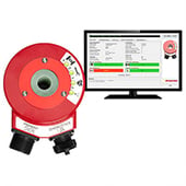
HS35iQ Hollow Shaft Quadrature Encoder
Programmable Quadrature Encoder with Specific Fault Detection Capabilities
Customize & Buy Now
View Key Product Features
- Up to 20,000 PPR
- Optical Sensing
- Up to IP67
Achieving higher resolution with Quadrature Encoders
When more resolution is needed, it is possible for the counter to count the leading and trailing edges of the quadrature encoder’s pulse train from one channel, which doubles (x2) the number of pulses per revolution. Counting both the leading and trailing edges of both channels (A and B channels) of a quadrature encoder will quadruple (x4) the number of pulses per revolution. This technique is known as interpolation and will depend on how the signal is decoded through the users drive, PLC, or Controller.
As a result, 10,000 pulses per turn can be generated from a 2,500 PPR quadrature encoder. Typically with a Dynapar encoder, this 4x signal will be accurate to better than ±1 count. Likewise, 40,000 pulses can be generated from a 10,000 PPR quadrature encoder.
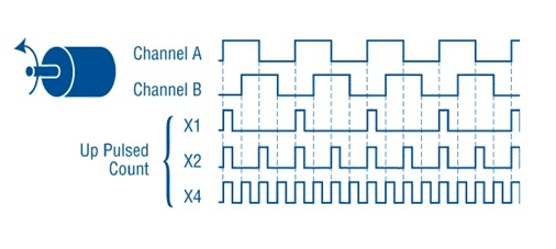
By triggering on the rising and falling edges of the pulse train, we can double or quadruple the counts per revolution from the same quadrature encoder disc.
This technique can be an effective way to increase resolution without changing the code disc. However, it requires a well-behaved square wave output for effective detection. Care should be taken with the output driver choice, particularly over long cable runs or noisy environments. The accuracy of the quadrature encoder output should also be considered, as this will also be multiplied by the encoding factor.
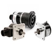
How to choose a Quadrature Encoder?
Like all encoders, choosing a quadrature encoder starts with your application. If your motor has a shaft, a shafted encoder with a coupler can be used. A hollow shaft encoder is another option mounted with the motor shaft going through the encoder for more accuracy. If your motor is used in a contaminated or dirty environment or you are using a large vector motor, a bearingless or magnetic encoder will provide the most reliable feedback.

Looking for a Custom Solution?
Tell us your requirements and our application engineers will help find the right solution today.
Contact Us →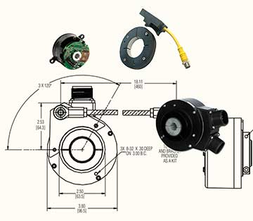
 {{else if (myEq content.heading "Absolute Encoders")}}
 {{/if}}