
What is a Resolver?
A resolver is an electromagnetic transducer that can be used in a wide variety of position and velocity feedback applications which includes light duty/servo, light industrial or heavy duty applications. Resolvers, known as motor resolvers, are commonly used in servo motor feedback applications due to their good performance in high temperature environments.
.jpg?width=300&height=272&name=Resolver-Photo(1).jpg)
Because the resolver is an analog device and the electrical outputs are continuous through one complete mechanical revolution, the theoretical resolution of a single speed resolver is infinite. Because of its simple transformer design and lack of any on board electronics, the resolver is a much more rugged device than most any other feedback device and is the best choice for those applications where reliable performance is required in those high temperature, high shock and vibration, radiation and contamination environments which makes the resolver the sensible design alternative for shaft angle encoding.

Resolver Design
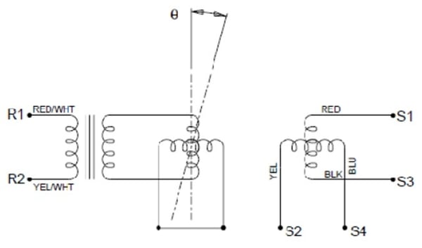
The resolver is a special type of rotary transformer that consists of a cylindrical rotor and stator. Both the rotor and the stator are manufactured with multi-slot laminations and two sets of windings. The windings are normally designed and distributed in the slotted lamination with either a constant pitch-variable turn or variable pitch-variable turn pattern. In either case, the winding distribution is in a sinusoidal pattern.
The windings for a single speed resolver create one complete Sine curve and Cosine curve in one mechanical revolution while the windings for a multi-speed resolver create multiple Sine and Cosine curves in one mechanical revolution. While a single speed provides absolute feedback and the multi-speed does not, the multi-speed does provide better accuracy. The number of speeds available is limited by the size of the resolver. The two sets of windings are positioned in the laminations at 90 degrees to each other. These are called the Sine and Cosine windings. One set of windings in the rotor are normally shorted internally to improve the accuracy. Learn more about resolver speeds and accuracy here
How Does a Resolver Work?
A resolver outputs signal by energizing the input phase of the resolver with an AC voltage (VAC) to induce voltage into each of the output windings. The resolver amplitude modulates the VAC input in proportion to the Sine and the Cosine of the angle of mechanical rotation. The resolver is sometimes known as an Analog Trigonometric Function Generator or a Control Transmitter. The function of the resolver is to resolve a vector into its components (Sine and Cosine). Electrical Zero (EZ) is defined as the position of the rotor with respect to the stator at which there is minimum voltage amplitude across the Sine winding and the maximum voltage amplitude across the Cosine winding when the input winding is excited with the rated voltage.

The rotor position or angle is simply the Arc tan of the voltage output of the Sine winding divided by the output of the Cosine winding. This ratio metric format provides an inherent noise reduction feature for any injected noise whose magnitude is approximately equivalent on both windings and also results in a large degree of temperature compensation. Learn more about resolver output here
There are 7 functional operating parameters which define the resolver operation. These are:
- Accuracy
- Input Excitation Voltage
- Input Excitation Frequency
- Input Current Maximum
- Transformation Ratio of Output Voltage to the Input Voltage
- Phase shift of the Output Voltage from the Input Voltage
- Null Voltage
Resolver Applications
The simplicity of the resolver design makes them reliable in many harsh environment and extreme applications. Common applications of resolvers include:
- Servo motor feedback
- Speed and position feedback in steel and paper mills
- Oil and gas production
- Jet engine fuel systems
- Aircraft flight surface actuators
- Communication position systems
- Control systems in land based military vehicles
Resolvers vs Encoders
With no onboard electronics, resolvers can survive extreme temperatures and tolerate shock and vibration, making resolvers suitable in applications where encoders would fail. As feedback devices, resolvers can be used as alternatives to both incremental encoders and absolute encoders. However, resolvers output an analog signal and require a separate analog-to-digital converter where encoders output digital signals.
For applications where radiation is present, resolves can be rad hardened to be used in these environments. Their lack of onboard electronics also provides an advantage in radiated environments.
Compared to absolute encoders, single-speed resolvers provide absolute position and can be used as absolute devices, making them alternatives when environment conditions do not allow for the use of absolute encoders.
Additional Resolver Resources
Learn how to specify resolver speed and accuracy here
Learn more about resolver output and voltage here
Download our white paper on the key differences between encoders and resolvers here
Download our white paper on how to specify the best resolver for your application here
Dynapar's Most Popular Resolvers
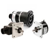
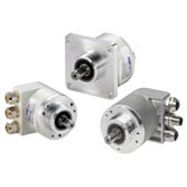
Dynapar offers frameless resolver and housed resolver options. Frameless resolvers with rotor and stator assemblies that can be housed in servo motors, direct drive motors, rotary platforms and more to provide motion feedback. Housed resolvers provide reliable feedback in a sealed package with various IP rated models.See our most popular resolver models:


{{#if customLayout}}
{{html customLayout}}
{{else}}
{{#each items}}
{{#if products.results.length}}
{{products.title}}
{{/if}}
{{#if (or categories.results.length content.results.length queries.results.length)}}
{{#each products.results}}
{{/each}}
{{#if queries.results.length}}
{{queries.title}}
{{/if}}
-
{{#each queries.results}}
- {{query}} {{/each}}
-
{{#each productSuggestedQueries.results}}
- {{query}} {{/each}}
-
{{#each contentSuggestedQueries.results}}
- {{query}} {{/each}}
-
{{#each categories.results}}
- {{html title}} {{/each}}
-
{{#each content.results}}
- {{html title}} {{/each}}
{{#if (eq title "Search within results")}}
Search Within Results
{{#if tooltip}}
{{else}}
{{title}}
{{#if tooltip}}
{{/if}}
{{#unless collapsed}}
{{#if searchable}}
{{/if}}
{{#if (eq type "checkbox")}}
{{/unless}}
{{#if (myEq attributes.type "Product")}}
{{#if (myEq attributes.is_family "No")}}

{{#if attributes.list_price}} {{#if attributes.leadtime}} Buy Now!
{{/if}} {{/if}} View Product Info
{{else}}

{{#if attributes.family_page_link}} View Series Info {{else}} More Info {{/if}}
{{/if}}
{{else if (myEq attributes.type "Content")}}
{{#if (myEq attributes.content_type "Page")}}
More Info
{{else if (myEq attributes.content_type "BlogPost")}}
More Info
{{else}}
UNKNOWN TYPE 2 (type:{{attributes.type}}, content_type:{{attributes.content_type}})
{{/if}}
{{else}}
UNKNOWN TYPE 1: (type:{{attributes.type}}, content_type:{{attributes.content_type}})
{{/if}}
{{#if attributes.family_id}}
{{attributes.family_id}}
{{/if}}
{{#if attributes.part_number}}
{{/if}}
{{#if (myEq attributes.consult_factory_price "1")}}
Consult Factory
{{else}}
{{#if (isNumber attributes.list_price)}}
{{currency attributes.list_price}} {{attributes.currency_code}}
{{/if}}
{{/if}}
{{attributes.description}}
{{#if (myEq attributes.consult_factory_leadtime "1")}}
Consult Factory
{{else}}
{{#if (isNumber attributes.leadtime)}}
{{isInt attributes.leadtime}} {{attributes.leadtime_period}}
{{/if}}
{{/if}}
{{#if attributes.data_sheet_link}}
Download Datasheet
{{/if}} {{#if attributes.installation_manual_link}} Download Installation Manual {{/if}}
{{/if}} {{#if attributes.installation_manual_link}} Download Installation Manual {{/if}}
{{#if attributes.list_price}} {{#if attributes.leadtime}} Buy Now!
{{/if}} {{/if}} View Product Info
{{#if attributes.family_id}}
{{attributes.family_id}}
{{else}}
{{/if}}
{{#if attributes.description}}
{{#if attributes.family_page_link}}
{{truncateWithMore attributes.description attributes.family_page_link}}
{{else}}
{{truncateWithMore attributes.description attributes.url_detail}}
{{/if}}
{{/if}}
{{#if attributes.data_sheet_link}}
Download Datasheet
{{/if}} {{#if attributes.installation_manual_link}} Download Installation Manual {{/if}}
{{/if}} {{#if attributes.installation_manual_link}} Download Installation Manual {{/if}}
{{#if attributes.family_page_link}} View Series Info {{else}} More Info {{/if}}
{{#if attributes.description}}
{{#if attributes.family_page_link}}
{{truncateWithMore attributes.description attributes.family_page_link}}
{{else}}
{{truncateWithMore attributes.description attributes.url_detail}}
{{/if}}
{{else if attributes.description_short}}
{{#if attributes.family_page_link}}
{{truncateWithMore attributes.description_short attributes.family_page_link}}
{{else}}
{{truncateWithMore attributes.description_short attributes.url_detail}}
{{/if}}
{{/if}}
{{#if attributes.data_sheet_link}}
Download Datasheet
{{/if}} {{#if attributes.installation_manual_link}} Download Installation Manual {{/if}}
{{/if}} {{#if attributes.installation_manual_link}} Download Installation Manual {{/if}}
More Info
{{#if strings.summary}}
{{strings.summary}}
{{/if}}
{{#if content.customHtml}}
{{html content.customHtml}}
{{/if}}
{{#if (myEq content.heading "Incremental Encoders")}}
 {{else if (myEq content.heading "Absolute Encoders")}}
 {{/if}}
{{else if (myEq content.heading "Absolute Encoders")}}
{{/if}}
{{searchResultsFor}}