BiSS Encoder Overview
BiSS encoders offer an open source interface for point-to-point or bus communication that sends full absolute position data whenever the controller polls the encoder, rather than just at startup.
Key features include:
- BiSS encoders use four data lines, one pair carrying data from the encoder and one carrying clock data to it, plus two power conductors. BiSS uses a variable clock rate of up to 10MHz.
- BiSS encoders can be connected either point-to-point or via a bus.
- BiSS allows easy recovery from momentary data dropouts during operation and is compatible with SSI and EnDat hardware, requiring only software changes.
- BiSS can address internal registers in the encoder that can be read by and written to by the master with data about the encoder itself (identification, device data, resolution, etc.)
- BiSS encoders can also carry other digital data (temperature, etc.) and transmit the data to the master on demand, without interfering with real-time operation.
Learn more about all absolute encoder interface protocols here
BiSS Encoder Communication Format
BiSS has two modes; sensor mode and register mode. In sensor mode, the sensor or encoder communicates in a manner similar to SSI. The master begins to send a stream of clock pulses. Eventually the data line level will drop low and data sampling will begin. The data can be received and clocked at 10MHz. Due to the transmission speed, many drives may not require additional analog incremental outputs to control motor speed. Since SSI has a slower max transfer rate of 1.5MHz, compared to 10MHz for BiSS encoders, the propagation and calculation delay is less than a full pulse width. This is how BiSS is capable of hardware compatibility with SSI. Only the data length and framework need to be changed in the software.
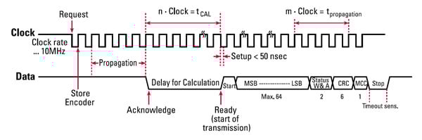
Figure 1: BiSS Encoder Communication Format
In register mode, the protocol modulates the clock pulse width to address specific slaves and parameters. This mode is unlike any other protocol. If in the sensor mode a warning or alarm bit is set high by the sensor or encoder, the end-user may access the register mode and find specifics on the alarm or warning. This might be an over-temperature warning or, in the case of an encoder, a disk pollution alarm. Dynapar has developed BiSS encoders with the ability to provide single step alarms in case improper position is being provided in sequence.
Looking for a Custom Solution?
Tell us your requirements and our application engineers will help find the right solution today.
Contact Us →
 {{else if (myEq content.heading "Absolute Encoders")}}
 {{/if}}