
Angle Encoders: How to Measure Angle Using Encoders
Angle encoders measure the rotational position of a load in relation to a shaft or point. The angle encoder provides output that corresponds to displacement and the reading device (PLC, counter, etc.) processes that data into angular readings. There are three approaches to measuring an angle with an encoder:
- Direct angle measurement with an encoder mounted to the pivot point of the load
- Indirect angle measurement with an encoder mounted to the motor driving rotation
- Indirect angle measurement with a multi-turn encoder mounted along the circumference of the load
Choose The Right Encoder IP Rating
Free White Paper: Understanding Encoder IP Ratings

Popular Angle Encoder Models:
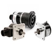
AD36 Absolute Encoder
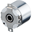
Compact high resolution absolute encoder.

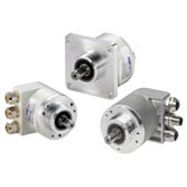
AI25 SSI Absolute Encoder
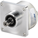
SSI Gray or Binary Interface absolute encoder.

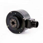
HS35R Hollow Shaft Encoder
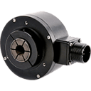
Heavy duty hollow shaft incremental encoder.

Direct Angle Measurement by Tracking the Load
To measure the angular displacement of the load directly, the encoder should be mounted on the center pivot point of the load. As the load turns, the encoder relays the signal to the receiving device. This data only consists of either displacement pulses (incremental encoder) or initial and final absolute positions (absolute encoder). The reading device, whether it is a drive, a controller, or some type of counter/display device, needs to process the raw data into useful information.
![]()
In the case of an incremental encoder, the angle α can be expressed as

where P equals the number of pulses and PPR equals pulses per revolution
In the case of an absolute encoder, the angle α can be expressed as

where C equals counts and CPR equals counts per revolution.
Choose The Right Encoder IP Rating
Free White Paper: Understanding Encoder IP Ratings
Indirect Angle Measurement by Tracking the Motor Shaft
It is also possible to measure the angular displacement of a load by monitoring the motor shaft or an Idler wheel. In this case, we get best results by turning the motor shaft a set number of times and correlating it to the displacement of the load to come up with a conversion factor.
![]()
This is the traditional use case for a rotary encoder. It has the benefit of improving motor performance through direct feedback. The drawback is that it may not accurately track the movement of the load. Mechanical compliance introduced by couplings, gearboxes, etc. can introduce errors like backlash and hysteresis. The conversion factor theoretically takes this into account, but mechanical effects can drift over time.
Indirect Measurement by Tracking the Edge of the Load
Some loads are incompatible with center-pivot encoder mounting. Satellite dishes, for example, need to be rotated to point in the direction of the signal of interest to a high degree of control. Both the mechanical design and the presence of electrical cabling passing up through the central shaft make it impossible to install an encoder at the pivot point to monitor position directly. Depending on the degree of control, an extremely high-resolution encoder may also be required. The solution is to track these devices along their circumference.
![]() In the indirect circumferential method, a geared wheel attached to a multi-turn absolute encoder engages with the circumference of the load to track its angular displacement. Learn more about single-turn vs multi-turn encoders here
In the indirect circumferential method, a geared wheel attached to a multi-turn absolute encoder engages with the circumference of the load to track its angular displacement. Learn more about single-turn vs multi-turn encoders here
As the band on the load moves past, it turns the wheel and the movement is registered by the encoder. The reduction ratio of the gearbox enables it to deliver a high number of rotations for every turn of the gear wheel. This delivers a final resolution RF given by:
![]()
where RB is the number of counts on the band and N is the reduction ratio of the gearbox on the multi-turn encoder. The contact may consist of a toothed gear wheel engaging with a toothed band on the load. Alternatively, it could be a friction contact from an encoder measuring wheel or even a belt.
Error sources include mechanical couplings, backlash from the gearbox, shaft runout and de-centering, belt slippage in the case of friction contacts, and others. The high reduction ratio of the gearbox minimizes the effect of mechanical error. The exception to this is friction in the gearing and seals of the gearbox. In this case, the impact of friction is multiplied by the number of turns.
Popular Angle Encoder Models:
AD36 Absolute Encoder
Compact high resolution absolute encoder.
AI25 SSI Absolute Encoder
SSI Gray or Binary Interface absolute encoder.
HS35R Hollow Shaft Encoder
Heavy duty hollow shaft incremental encoder.
Incremental vs Absolute Angular Encoders
Incremental angle encoders can only register displacement from some arbitrarily defined home position that is established at startup. This home position, usually referred to as an index, creates only one pulse throughout one complete rotation of the code disc. This enables the device processing the encoder signal to track the number of full turns of the encoder disc from the home position. However, the index pulse is not unique so the number of full rotations counted is often lost if the device is powered down and it must be rehomed on startup.
An absolute angle encoder outputs a unique digital word for each position of the code disc. Multi-turn absolute angle encoders also track the total number of full revolutions with a digital word. Thus, there is no need for homing and the information is not lost when the device is powered down. The moment an absolute angle encoder is turned on, it can report exactly where it is by reading the digital word of that particular angle.
Achieving Higher Resolution with Quadrature Angle Encoders
Interpolating the signal of a quadrature angle encoder can also deliver a significant performance boost, depending on the implementation. If the processor of the receiving device treats the leading edge and trailing edge of both the A pulse and the B pulse as individual pulses, it quadruples the effective resolution of the angle encoder. For example, this interpolation technique could enable an industry standard 1024 PPR quadrature encoder to resolve angles of just 0.088 degrees.
However, it should be noted that any errors will be multiplied by along with the resolution. These can degrade performance, which means that an attempt to increase system accuracy by creating higher resolutions through interpolation might have the unintended result of amplifying an error and degrading system performance. This is an example of how higher resolution does not improve accuracy. Learn more about encoder accuracy vs encoder resolution here.
Quadrature angle encoders also allow the direction of that rotation to be monitored. In a quadrature encoder, the disc has two separate sets of markings (channels) that are offset so that the signal for the B channel is 90 degrees out of phase (in quadrature) with that of the A channel. This enables the receiving device to determine the direction of rotation.

Looking for a Custom Solution?
Tell us your requirements and our application engineers will help find the right solution today.
Contact Us →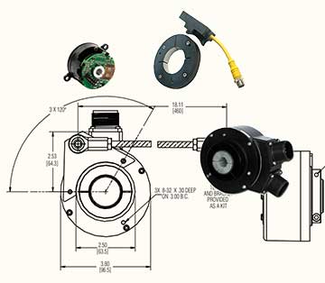
{{#if customLayout}}
{{html customLayout}}
{{else}}
{{#each items}}
{{#if products.results.length}}
{{products.title}}
{{/if}}
{{#if (or categories.results.length content.results.length queries.results.length)}}
{{#each products.results}}
{{/each}}
{{#if queries.results.length}}
{{queries.title}}
{{/if}}
-
{{#each queries.results}}
- {{query}} {{/each}}
-
{{#each productSuggestedQueries.results}}
- {{query}} {{/each}}
-
{{#each contentSuggestedQueries.results}}
- {{query}} {{/each}}
-
{{#each categories.results}}
- {{html title}} {{/each}}
-
{{#each content.results}}
- {{html title}} {{/each}}
{{#if (eq title "Search within results")}}
Search Within Results
{{#if tooltip}}
{{else}}
{{title}}
{{#if tooltip}}
{{/if}}
{{#unless collapsed}}
{{#if searchable}}
{{/if}}
{{#if (eq type "checkbox")}}
{{/unless}}
{{#if (myEq attributes.type "Product")}}
{{#if (myEq attributes.is_family "No")}}

{{#if attributes.list_price}} {{#if attributes.leadtime}} Buy Now!
{{/if}} {{/if}} View Product Info
{{else}}

{{#if attributes.family_page_link}} View Series Info {{else}} More Info {{/if}}
{{/if}}
{{else if (myEq attributes.type "Content")}}
{{#if (myEq attributes.content_type "Page")}}
More Info
{{else if (myEq attributes.content_type "BlogPost")}}
More Info
{{else}}
UNKNOWN TYPE 2 (type:{{attributes.type}}, content_type:{{attributes.content_type}})
{{/if}}
{{else}}
UNKNOWN TYPE 1: (type:{{attributes.type}}, content_type:{{attributes.content_type}})
{{/if}}
{{#if attributes.family_id}}
{{attributes.family_id}}
{{/if}}
{{#if attributes.part_number}}
{{/if}}
{{#if (myEq attributes.consult_factory_price "1")}}
Consult Factory
{{else}}
{{#if (isNumber attributes.list_price)}}
{{currency attributes.list_price}} {{attributes.currency_code}}
{{/if}}
{{/if}}
{{attributes.description}}
{{#if (myEq attributes.consult_factory_leadtime "1")}}
Consult Factory
{{else}}
{{#if (isNumber attributes.leadtime)}}
{{isInt attributes.leadtime}} {{attributes.leadtime_period}}
{{/if}}
{{/if}}
{{#if attributes.data_sheet_link}}
Download Datasheet
{{/if}} {{#if attributes.installation_manual_link}} Download Installation Manual {{/if}}
{{/if}} {{#if attributes.installation_manual_link}} Download Installation Manual {{/if}}
{{#if attributes.list_price}} {{#if attributes.leadtime}} Buy Now!
{{/if}} {{/if}} View Product Info
{{#if attributes.family_id}}
{{attributes.family_id}}
{{else}}
{{/if}}
{{#if attributes.description}}
{{#if attributes.family_page_link}}
{{truncateWithMore attributes.description attributes.family_page_link}}
{{else}}
{{truncateWithMore attributes.description attributes.url_detail}}
{{/if}}
{{/if}}
{{#if attributes.data_sheet_link}}
Download Datasheet
{{/if}} {{#if attributes.installation_manual_link}} Download Installation Manual {{/if}}
{{/if}} {{#if attributes.installation_manual_link}} Download Installation Manual {{/if}}
{{#if attributes.family_page_link}} View Series Info {{else}} More Info {{/if}}
{{#if attributes.description}}
{{#if attributes.family_page_link}}
{{truncateWithMore attributes.description attributes.family_page_link}}
{{else}}
{{truncateWithMore attributes.description attributes.url_detail}}
{{/if}}
{{else if attributes.description_short}}
{{#if attributes.family_page_link}}
{{truncateWithMore attributes.description_short attributes.family_page_link}}
{{else}}
{{truncateWithMore attributes.description_short attributes.url_detail}}
{{/if}}
{{/if}}
{{#if attributes.data_sheet_link}}
Download Datasheet
{{/if}} {{#if attributes.installation_manual_link}} Download Installation Manual {{/if}}
{{/if}} {{#if attributes.installation_manual_link}} Download Installation Manual {{/if}}
More Info
{{#if strings.summary}}
{{strings.summary}}
{{/if}}
{{#if content.customHtml}}
{{html content.customHtml}}
{{/if}}
{{#if (myEq content.heading "Incremental Encoders")}}
 {{else if (myEq content.heading "Absolute Encoders")}}
 {{/if}}
{{else if (myEq content.heading "Absolute Encoders")}}
{{/if}}
{{searchResultsFor}}