{{#if (isNumber attributes.leadtime_business_days)}}
~{{attributes.leadtime_business_days}} Business Days
{{else}}
{{attributes.leadtime_business_days}}
{{/if}}
How to Measure Linear Distance with Rotary Encoders
Rotary encoders inherently monitor the displacement or position but can be used to measure linear distance by calculating the number of pulses compared to the known number of pulses per arc length and designed into a system that returns linear feedback.
There are three basic approaches:
Direct measurement of load using a draw-wire encoder
Direct measurement of load using a follower-wheel encoder
Indirect measurement of load using an encoder on the motor shaft
For a detailed discussion of distance measurement using draw-wire encoders, see the articleHow to Measure Distance with Draw Wire Encoders. Here, we focus on length-measuring applications, reviewing best practices for specifying and implementing these systems.
Length measuring applications are common in industry, from cutting pieces of plastic web for potato-chip bags to sawing rough planks into two by fours, to tracking distance traveled along a curb by road-paving equipment. Each use case provides its own set of requirements for feedback.
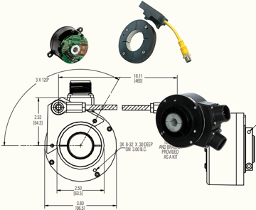
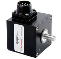
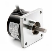
Direct Measurement Using a Measuring Wheel Encoder
A measuring wheel or follower-wheel encoder consists of an encoder wheel mounted on the shaft of an encoder (or vice versa). The wheel interfaces directly with the surface of the material being measured. As the material moves relative to the encoder, the wheel turns, rotating the encoder code disc and generating a signal.
To calculate the length traveled L (inches) using the output from anincremental encoder, we start by calculating the number of pulses per 1 in. arc length (PPI):
where PPR is pulses per revolution and D is follower wheel diameter (inches). Then length L is given by:
Depending on the application, the encoder measuring wheel may be fixed, as for a paper measuring system in a converting line or a printing line. Alternatively, the follower wheel may be in motion while the material being evaluated remains fixed. Examples of this case include roadways for paving applications or the side of a hoistway in an elevator shaft.
How to Maintain Measurement Accuracy with Wheel Encoders
The most important aspect of measuring length with a measuring wheel encoder is avoiding slippage. The encoder wheel needs an adequate coefficient of friction relative to the material being evaluated. The coefficient of friction can be adjusted by a combination of the structure of the wheel surface and its materials. In the case of measuring lengths of silk fabric in a large industrial cloth-cutting operation, the wheel might be fitted with soft rubber fingers. In a hay baler, the device would use wheels fitted with long metal teeth. The spikes catch in the hay, turning to measure out the length of a bale so that the machine knows when to cut it and band it. On a machine for applying asphalt sealant to roadways, the follower wheel may simply be finished with a treaded O-ring.
Another way to prevent slippage is by adding a preload. The preload needs to be carefully balanced, however. If it is too low, the wheel might skip or slip, resulting in lost motion. If the preload is too high, it can damage the product being measured. It can also apply excess load to the bearing, resulting in increased wear and, potentially, premature failure.
Avoiding Overhung Loads
Overhung loads can be a risk in follower-wheel applications. Excessive overhung loads make the bearing a fulcrum and therefore susceptible to premature failure.
A simple example of an overhung load is in a belt and pulley system. In this use case, the unit would apply a toothed follower wheel that would engage with the belt. The belt tension controls the load on the wheel: If the belt is too loose, the wheel can slip; if it is too tight, it has the potential to damage the encoder.
Another common use case would be tracking the movement of a gantry. The encoder would be mounted on the trolley with the wheel pressed against the frame.
Rack and pinion designs require care to avoid damaging the equipment or potentially compromising the measurement. Here, too, excess overhung load can damage the encoder. The problems can be more subtle than that, however. If the rack is mounted to the machine frame, it can transfer machine vibration to the encoder via the pinion. This could introduce an artifact into the data at the resonant frequency of the machine.
Even in the absence of an overhung load, problem applications abound, such as in therailroad industrywhere maintenance vehicles use follower-wheel encoders to measure track length. Follower wheels in these types of systems should be implemented with care. The encoder shaft should not carry the weight of the assembly. Depending on the condition of the equipment and the track, this arrangement can apply a high force load to the encoder shaft.
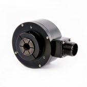
One solution is to use a dual-shaft encoder and mount a follower wheel on either side. For an application involving higher shock and vibration, a hollow-bore encoder might prove more rugged. In this implementation, a fifth wheel or idler wheel with an extended shaft is added to the vehicle and the encoder is mounted on the shaft. The bearing of the wheel assembly takes the load, saving the encoder.
In some cases, there is no workaround. In these instances, harsh-duty encoders provide the best solutions.
Indirect Measurement via Motor Shaft Monitoring
Not every application enables the load to be measured directly. In destructive testing, for example, a pair of grippers are used to pull apart the test piece until it fails. In this case, the encoder is mounted on the motor shaft to track rotations. This data can be used with a variation of equation 1 and equation 2 to yield the displacement of the grippers.
Mounting the encoder on the motor shaft is a common approach. It is simpler to execute than a follower wheel, with fewer potential mounting errors. On the downside, mechanical elements like gearboxes and couplers can introduce issues such as compliance, backlash, and hysteresis. Actuators can also introduce mechanical slop as well as practical problems. Screw-type actuators with finer thread pitches have a very high number of turns per inch. This can present a challenge even for multi-turn absolute encoders.
Length measurement has a wide range of use cases, each with its own specific requirements. By taking advantage different implementations and a wide variety of encoders, engineers and maintenance staff can satisfy the needs of the application. Pay attention to these tips and followbest practices for encoder wiringand installation and your system will operate as desired.


.jpg "Rotary Encoders Used In Sawmill Photo")