Encoder Output: How to Specify the Right Output Driver
An encoder output driver amplifies and processes raw encoder signal into square-wave signals that can be transmitted to the readout device or drive.
 For incremental encoders, there are 3 types of encoder output:
- Open-collector encoder output
- Push-pull encoder output
- Differential line driver encoder output
For absolute encoders there are four major encoder output options:
- Parallel output
- Serial output (point-to-point interfaces such as SSI and BiSS are examples)
- Field bus protocols (CanOpen and DeviceNet are examples)
- Ethernet network based protocols (EtherNet/IP, Profinet or EtherCAT are examples)
This page focuses on incremental encoder output. Learn more about absolute encoder output types here
Free White Paper Resources:
❮
Encoder IP Ratings
How to Choose Encoder Output
Encoders vs Resolvers


❯
Incremental Encoder Output
Incremental encoders can be connected to the control/counter via single ended (one wire per channel) or differential (two-wires per channel) schemes. The advantage of a differential signal is that it offers greater resistance to electromagnetic interference. This is done by generating two signals and referencing them to each other instead of ground. A disadvantage is the increased cost of running extra wire.
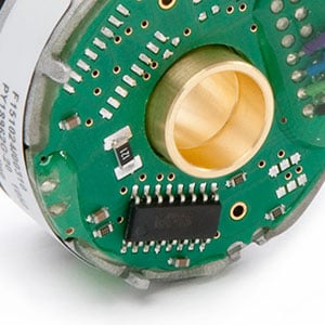
These analog encoders require output drivers to convert the photodiode output to a square wave signal and send it across to the control/counter.
Electrical I/O can be classed as sinking or sourcing.
- Sinking I/O: A sinking device provides a path to ground
- Sourcing I/O: A sourcing device supplies voltage
Although exceptions exist, an ideal circuit matches a sourcing input (e.g., PLC) with a sinking output (e.g., encoder). Similarly, a sinking input should be paired with a sourcing output.
Sinking outputs are typically based on NPN transistors, while sourcing outputs are typically based on PNP transistors. The three common types of encoder output drivers corresponding to these devices are:
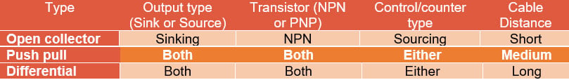
The three common output types are open-collector (pull), single-ended (push-pull), and differential line drivers (push-pull). Let’s consider the three categories.
Open Collector Encoder Output
Simple and economical, open-collector output drivers are sinking output drivers designed for use with sourcing controls. Open-collector output drivers are based on NPN transistors. When the transistor is on, the encoder acts as a current sink. When the transistor is off, the output is left floating (open). Because the transistor output is left open, open-collector drivers need to be used with an appropriately sized pull-up resistor. This resistor “pulls” the signal up to a designated voltage, switching the output on and off to generate the square-wave signal.
Because an open collector is a sinking device, it cannot source or “push” current, making it unsuitable for longer cable runs or high-noise environments. Another factor to consider is that open collector output works best at lower resolutions. This is because the pull-up resistor alters the speed (slew rate) at which pulses are generated. As a result, the open-collector output should not be used with differential or complementary encoder signals (A, A-not, B, B-not). However, if short cable runs and a low noise environment are application characteristics, the open-collector output is probably the more economical choice.
Push-Pull Encoder Output
Push-pull output drivers, also referred to as totem pole drivers or single-ended drivers, incorporate both NPN and PNP transistors. This design finds the attributes of both sinking and sourcing outputs in a single device. This architecture makes them compatible with both sinking and sourcing controls/counters. The characteristic totem-pole appearance of the circuit diagram gives this driver its nickname.
By eliminating the pull-up resistor used in open collector outputs, push-pull outputs use less power and are therefore good options for battery-operated designs. For only a modest price premium, push-pull output drivers provide an extremely flexible solution that is compatible with most systems.
Differential Line Driver Encoder Output
Differential line driver encoder output has become the go-to for a range of industrial applications, particularly in high-noise environments. A line driver can actively force the output high and low, which enables it to sink and source current from the load. As a result, it can generate higher current, supporting longer transmission distances. As the name implies, this kind of output chip sources or “drives” current down the line.
Consider an encoder providing feedback to a counter with an internal resistance of 10 kΩ. The encoder is powered by a 12 VDC power source. With open-collector output used in conjunction with a 2 kΩ pull up resistor, the voltage at the point of termination would drop to 10 VDC because of the high ratio between pull up resistor and internal resistance of the counter. If we switch to line driver output, this is no longer a problem. As long as the current does not exceed the capabilities of the line driver, the output voltage will remain constant at 12 VDC.
Although a differential line driver can be used in a single-ended format (i.e. push-pull output), they are most commonly used with complementary or differential signals for noise cancellation.
Common examples of line driver outputs include:
- 7272 encoder line driver output
- 7273 encoder line driver output
- 4469 encoder line driver output
- High Power MOSFET line driver output
Learn more about encoder line drivers and how to select them here
Example of Choosing the Wrong Line Driver
It’s essential to choose an encoder line driver with sufficient current capability. All cables have a certain degree of capacitance that essentially increases the amount of current required to charge them. This looks like a current spike to the line driver. If the line driver is not rated to handle that type of current demand, it will respond by dropping the voltage. The effect on the output pulse stream will be a longer rise time on the leading edge of the square wave and a similar rounding effect on the falling edge of the square wave (see figure below).
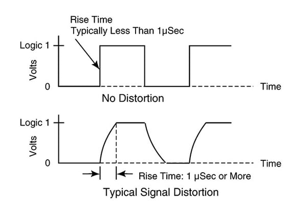
Image: A sudden spike in current draw caused by high cable capacitance can cause the line driver to reduce voltage in compensation. This increases the rise time for the pulse, converting it from a clean square wave (top) to a smeared pulse (bottom).
This can introduce errors, especially for readout devices triggering on the rising and falling edges of the pulses from quadrature encoders. The solution to this problem is to choose a line driver rated for a higher current. This will lead to output that more closely resembles a clean square wave.
Related Articles
Learn more about absolute encoder interface protocols
See other common encoder signal issues and how to diagnose them here
Looking for a Custom Solution?
Tell us your requirements and our application engineers will help find the right solution today.
Contact Us →
 {{else if (myEq content.heading "Absolute Encoders")}}
 {{/if}}