In this example the fault output from an HS35IQ encoder was connected to a Rockwell PLC. A simple single line of ladder logic was used to read the fault line from the encoder and turn on an LED when a fault is present. The LED is just an easy way to indicate the fault was successfully read from the encoder but other solutions such as alerting maintenance are possible by utilizing the fault output function.
Hardware Setup
The following components were used to test this example:
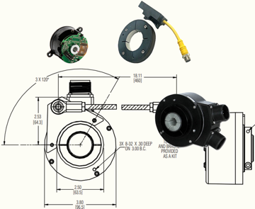
- HS35iQPROGR81721R2 encoder with 2.2k load resistors
- L27ERM-QBFC1B PLC
- 24V DC Power supply
- LED with current limiting resistor
The supply terminals for the PLC and the encoder were both connected to the same 24V DC power supply. The 24V power supply was also connected to the +V and COM0 connections on the “DC OUT” port included with the PLC. The anode or positive side of the LED had a resistor connected in series to limit the current supplied from the PLC output. The LED/resistor pair was connected to DC OUT 08 and COM. The fault output from the encoder was connected to DC IN 00. COM0 of “DC IN” was also tied to common (COM) of the PLC and encoder. See the wiring diagram in Figure 1.
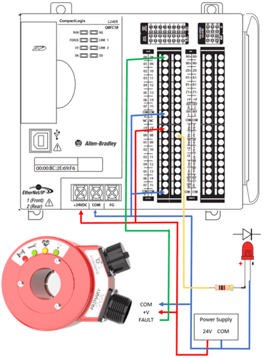 Figure 1. Wiring diagram for example
Software Setup
The routine written to read the fault output and turn on the LED is shown in Figure 2.
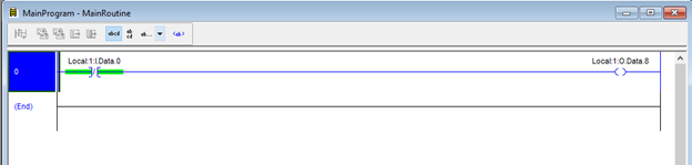 Figure 2. PLC software routine
An Examinine Off was used as the fault output is high during non-fault conditions and transitions to low when a fault occurs. The routine simply reads the status of the fault output on DC IN 0 and will energize DC OUT 08 connected to the LED if a low condition is read.
Testing
After everything was connected properly, the program was downlaoded to the PLC and it was set to run mode. To test proper functionality a cable fault was triggered by detaching the load resistor from one of the encoder outputs (A/B/Z). The cable fault LED on the encoder transitions to RED at the same time the LED connected to the PLC turns on (Figure 2). After the fault is corrected the cable fault LED on the encoder turns GREEN and the LED on the PLC turns off (Figure 3).
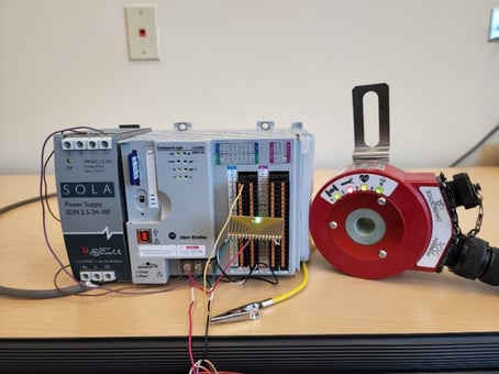 Figure 3. PLC indicating active fault output
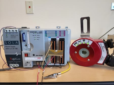 Figure 4. PLC indicates inactive fault output