
Specifying for Encoder Shock and Vibration
Industrial environments frequently expose equipment to high degrees of shock and vibration. This can impact performance and damage the device itself. Here, we discuss the trade-offs involved in choosing an encoder for a high shock-and-vibration environment and how to ensure appropriate lifetime and performance for the application.
Encoder Essentials White Paper
Encoder Mounting. How to Optimize the Life and Performance of Rotary Encoders
There are three key factors to consider when specifying for an application with high levels of encoder shock and encoder vibration:
- Encoder sensor engine: optical versus magnetic
- Encoder disk material: glass, metal, Mylar
- Encoder components: bearings, connectors, etc.
Encoder Sensor Engine
Encoders can be divided into optical and magnetic sensing engines. The most common type of optical encoder consists of a source (typically an LED), a detector, and a thin patterned code disk that passes between them.
Optical encoders can be extremely high resolution, making them essential for scientific applications and for specialty manufacturing like semiconductor fabrication. They can be vulnerable to shock and vibration, however. The air gaps between the disk and the source/detector can be as small as 0.020”. Excessive shock and vibration can introduce misalignments that can bring these components into contact, causing damage or even catastrophic failure.
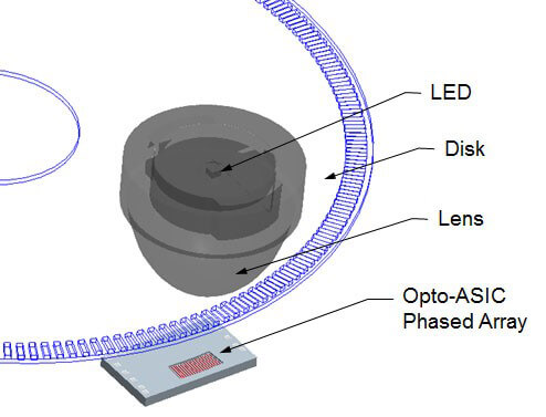
Phased-array optical encoders provide an alternative. As the name suggests, phased-array encoders use an array of detectors to capture the signal. This helps average out signal variation due to encoder shock or encoder vibration. The solid-state nature of the detector array also makes it less vulnerable to damage. Phased-array optical encoders are available rated for 400G shock and 20G vibration and are used in Dynapar encoders such as the HS35R heavy duty optical encoder
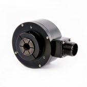
For the most difficult environments, a magnetic encoder may be the best choice. Magnetic encoders operate analogously to rotating optical encoders, although they are based on a metal wheel patterned with alternating magnetic domains. They tend to be much more robust than optical encoders and less vulnerable to encoder shock and encoder vibration. The devices are noncontact and the magnetic wheel and detectors are widely separated. Magnetic encoders designed with wide air gaps have significantly greater clearance such as the NorthStar RIMTach RT8 magnetic encoder
The trade-off is that the magnetic wheel cannot be patterned as densely as the code wheel on the optical encoder. As a result, magnetic encoders cannot match the resolutions of optical designs.
Encoder Disk Material
Optical encoders use three different types of disk materials: glass, metal, and Mylar. The choice of disk involves the trade-off between performance and response to shock and vibration as well as other environmental factors. For direct read encoders (not including quadrature interpolation to multiple resolution) Dynapar offers up to 10,000 PPR for encoders with glass disks, 5000 PPR Mylar disks and up to 2540 PPR for encoders with metal disks.
Although metal disks are very robust when exposed to high shock loads, they have an upper limit on resolution. Lithographically patterned glass disks provide higher resolution but they are vulnerable to encoder shock and can shatter. Mylar provides a better choice. There is a common misconception that glass out performs Mylar but this is incorrect. Mylar code disks deliver the highest resolution in optical encoders while remaining extremely robust.
Mylar code disks do come with a caveat, however. The material can be damaged by excess heat, discoloring or even distorting. For success, the encoder should be rated for the full set of conditions of the application.
Encoder components
Choosing the appropriate sensor engine and disk material represents only part of encoder specification. An encoder is a system and a system is only as effective as its weakest link. For an encoder to perform reliably, support components like cabling and bearings need to be chosen with the environment in mind.
An encoder can’t operate if the cabling has vibrated loose. Choose latching connectors that will remain in contact even after prolonged encoder vibration. Depending on the amplitude, frequencies, and durations, wiring may need screw-in connectors or direct wire contact to the terminals.
Cabling is not the only element vulnerable to connection issues. Prolonged vibration can fracture the solder joints on the PCB that holds the electronics. Even the wires within the cabling that link to the connector might fracture. For this specific reason, Dynapar’s magnetic encoders have fully encapsulated electronics.
Avoid bearings when possible. High levels of vibration can alter the loading of a bearing. This causes uneven wear, which can lead to premature bearing failure and is another reason why bearingless magnetic encodes are preferred in harsh environments such as paper and steel mills.
The Effects of Shock and Vibration on Encoder Signal
All that shaking does more than simply put the operation of an encoder at risk. Shock and vibration can compromise performance. Because magnetic encoders are so robust, they may not display physical effects of the vibration. The problems may show up in the signal, however.
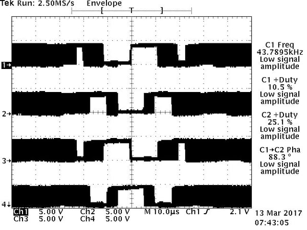
Vibration shows up in the signal as excess noise, manifesting as jitter. This is a different type of jitter from the one commonly caused by disk decentration. Decentration jitter typically shows up on only one channel while the other channel signal looks fine. Jitter caused by excess system vibration shows up on all channels. See an example of encoder jitter and compare it to encoder vibration caused by a lose coupling
Extremely high shock could misalign the wheel or code disk, which could also affect signal quality. It could result in excessive jitter on all channels and/or change in phasing between two channels.
Encoder Testing Methodology for Shock and Vibration
When choosing an encoder for high shock and vibration environments, data sheets are not enough. Designs need to be rigorously tested. Dynapar encoders are tested to MIL-STD-202 which requires techniques like sweep testing. In this process, the encoder is exposed to a specified period of sinusoidal vibration at distinct frequencies across a given range. An encoder qualified for 20Gs at 5 to 2000 Hz, for example, would be vibrated for 24 ten-minute sweeps along all three axes for a total duration of 12 hours. A vendor should have detailed results on test protocol and performance for every design.
Like all things in engineering, choosing an encoder for rugged environments involves trade-offs. The points above give general guidelines. Specialized applications such as those requiring very high resolution for harsh environments will push these technologies to their limits. In some cases, OEMs need to resign themselves to more frequent replacement of their feedback device. In most cases, however, working closely with the vendor and informing them of all specialty requirements will result in a solution that can satisfy the needs of the application.
Looking for a Custom Solution?
Tell us your requirements and our application engineers will help find the right solution today.
Contact Us →
{{#if customLayout}}
{{html customLayout}}
{{else}}
{{#each items}}
{{#if products.results.length}}
{{products.title}}
{{/if}}
{{#if (or categories.results.length content.results.length queries.results.length)}}
{{#each products.results}}
{{/each}}
{{#if queries.results.length}}
{{queries.title}}
{{/if}}
-
{{#each queries.results}}
- {{query}} {{/each}}
-
{{#each productSuggestedQueries.results}}
- {{query}} {{/each}}
-
{{#each contentSuggestedQueries.results}}
- {{query}} {{/each}}
-
{{#each categories.results}}
- {{html title}} {{/each}}
-
{{#each content.results}}
- {{html title}} {{/each}}
{{#if (eq title "Search within results")}}
Search Within Results
{{#if tooltip}}
{{else}}
{{title}}
{{#if tooltip}}
{{/if}}
{{#unless collapsed}}
{{#if searchable}}
{{/if}}
{{#if (eq type "checkbox")}}
{{/unless}}
{{#if (myEq attributes.type "Product")}}
{{#if (myEq attributes.is_family "No")}}

{{#if attributes.list_price}} {{#if attributes.leadtime}} Buy Now!
{{/if}} {{/if}} View Product Info
{{else}}

{{#if attributes.family_page_link}} View Series Info {{else}} More Info {{/if}}
{{/if}}
{{else if (myEq attributes.type "Content")}}
{{#if (myEq attributes.content_type "Page")}}
More Info
{{else if (myEq attributes.content_type "BlogPost")}}
More Info
{{else}}
UNKNOWN TYPE 2 (type:{{attributes.type}}, content_type:{{attributes.content_type}})
{{/if}}
{{else}}
UNKNOWN TYPE 1: (type:{{attributes.type}}, content_type:{{attributes.content_type}})
{{/if}}
{{#if attributes.family_id}}
{{attributes.family_id}}
{{/if}}
{{#if attributes.part_number}}
{{/if}}
{{#if (myEq attributes.consult_factory_price "1")}}
Consult Factory
{{else}}
{{#if (isNumber attributes.list_price)}}
{{currency attributes.list_price}} {{attributes.currency_code}}
{{/if}}
{{/if}}
{{attributes.description}}
{{#if (myEq attributes.consult_factory_leadtime "1")}}
Consult Factory
{{else}}
{{#if (isNumber attributes.leadtime)}}
{{isInt attributes.leadtime}} {{attributes.leadtime_period}}
{{/if}}
{{/if}}
{{#if attributes.data_sheet_link}}
Download Datasheet
{{/if}} {{#if attributes.installation_manual_link}} Download Installation Manual {{/if}}
{{/if}} {{#if attributes.installation_manual_link}} Download Installation Manual {{/if}}
{{#if attributes.list_price}} {{#if attributes.leadtime}} Buy Now!
{{/if}} {{/if}} View Product Info
{{#if attributes.family_id}}
{{attributes.family_id}}
{{else}}
{{/if}}
{{#if attributes.description}}
{{#if attributes.family_page_link}}
{{truncateWithMore attributes.description attributes.family_page_link}}
{{else}}
{{truncateWithMore attributes.description attributes.url_detail}}
{{/if}}
{{/if}}
{{#if attributes.data_sheet_link}}
Download Datasheet
{{/if}} {{#if attributes.installation_manual_link}} Download Installation Manual {{/if}}
{{/if}} {{#if attributes.installation_manual_link}} Download Installation Manual {{/if}}
{{#if attributes.family_page_link}} View Series Info {{else}} More Info {{/if}}
{{#if attributes.description}}
{{#if attributes.family_page_link}}
{{truncateWithMore attributes.description attributes.family_page_link}}
{{else}}
{{truncateWithMore attributes.description attributes.url_detail}}
{{/if}}
{{else if attributes.description_short}}
{{#if attributes.family_page_link}}
{{truncateWithMore attributes.description_short attributes.family_page_link}}
{{else}}
{{truncateWithMore attributes.description_short attributes.url_detail}}
{{/if}}
{{/if}}
{{#if attributes.data_sheet_link}}
Download Datasheet
{{/if}} {{#if attributes.installation_manual_link}} Download Installation Manual {{/if}}
{{/if}} {{#if attributes.installation_manual_link}} Download Installation Manual {{/if}}
More Info
{{#if strings.summary}}
{{strings.summary}}
{{/if}}
{{#if content.customHtml}}
{{html content.customHtml}}
{{/if}}
{{#if (myEq content.heading "Incremental Encoders")}}
 {{else if (myEq content.heading "Absolute Encoders")}}
 {{/if}}
{{else if (myEq content.heading "Absolute Encoders")}}
{{/if}}
{{searchResultsFor}}