Free White Paper Resources:
❮
Encoder Mounting
Encoder Output
IP Rating


❯
How Does an Optical Encoder Work?
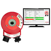
The working principle of optical encoders is to use light to detect the position or motion of an object and convert it into an electrical signal. The encoder consists of a light source, a sensor, and a rotating or linear code disk.
As the disk moves, the light source shines through the disk onto the sensor. The sensor detects the pattern of light and dark areas that the sensor and converts into an electrical signal. These offset signals can provide precise motion information, including speed. Some types of encoders utilize multiple signal outputs to create a more stable signal.
Optical encoders create signals that an integrated circuit processes into digital feedback. The number of slots on the disk and precision of the motion sensor determine accuracy and resolution of the encoder.
What is an Optical Encoder?
An optical encoder is a motion sensing device that utilizes light to convert mechanical motion into electrical pulse signals. It provides accurate position information in industrial applications like robotics, CNC machines, and motor control systems. Accurate motion details, like speed, are achieved sensors that give slightly different signals. They offer high accuracy, resolution, and reliability, and can operate in harsh environments.
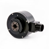
HS35R Hollow-shaft Incremental Optical Encoder
Reliable Hollow-Shaft Encoder Offers Extreme Performance for Heavy Duty Applications
Customize & Buy Now
View Key Product Features
- Up to 5000 PPR
- Optical Sensing
- Up to IP67
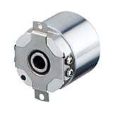
AD36 Absolute Hollowshaft Optical Encoder
1.5" OD Compact Hollow-Shaft Absolute Encoder with Up to 22 Bits ST and 12 Bit MT
Customize & Buy Now
View Key Product Features
- Up to 22 bit ST, 12 bit MT
- Optical Sensing
- Up to IP40
HS35iQ Programmable Optical Encoder
Programmable Hollow Shaft Optical Encoder with Specific Fault Detection Capabilities
Customize & Buy Now
View Key Product Features
- Up to 20,000 PPR
- Optical Sensing
- Up to IP67
What are the Types of Optical Encoders?
Absolute optical encoders use light to determine the control information. Masked and phased- array are the two types of optical encoders.
Masked Optical Rotary Encoders
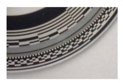
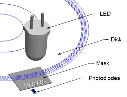
Masked optical encoders have four components: a light source, a sensor, a movable disk, and a fixed mask. The LED light shines through one side of the optical shaft encoder, and the encoder disk has a series of tracks on it.
The mask has a corresponding track for every track on the disk of the optical encoder. The tracks of the mask have many small perforations, called windows. The windows that are open versus closed during rotation determine the position of the optical shaft encoder.
Each arc in the rotation indicates a different position and has a different pattern of open/closed windows. The sensor behind the mask identifies the optical encoders’ current pattern. Each sensor represents one single signal for the optical encoder.
Phased- Array Optical Rotary Encoders
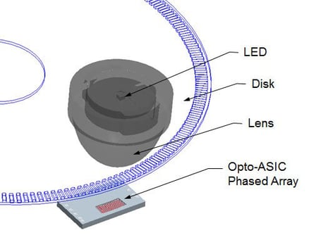
Phased-array optical encoders are even more reliable than masked optical encoders. They use multiple signal outputs to average together to create a single signal that is delivered by the engine. These multiple signals that are used by an optical shaft encoder are called the array.
By using averages instead of a single reading, phased-array optical encoders have much more stable signals. This means they can be used in less stable environments, such as mining or heavy manufacturing, where vibrations or shock could affect a traditional masked optical shaft encoder. They require less precision during installation than traditional masked optical encoders.
Understanding the pros and cons of different encoders can help determine the best encoder for each application. Optical encoders, both masked and phased-array, have many advantages over other types of encoders.
Looking for a Custom Solution?
Tell us your requirements and our application engineers will help find the right solution today.
Contact Us →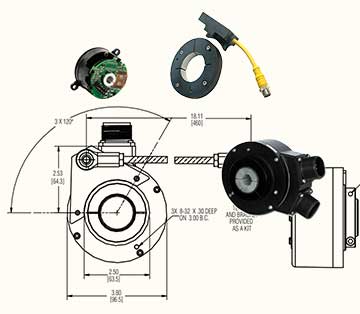
 {{else if (myEq content.heading "Absolute Encoders")}}
 {{/if}}