

Encoder Signal Duty Cycle and Symmetry
With the exception of the index channel, the channels of an incremental encoder code disc are patterned to generate a signal with a 50-50 duty cycle (see below). That means that 50% of the waveform should be high (0° to 180°) and 50% should be low (180° to 360°). In other words, it should be symmetrical.
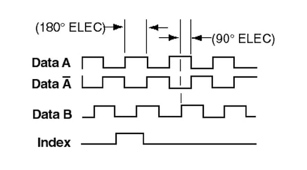
Encoder Signal Phasing
In many cases, encoder performance depends on the relative phasing between channels. Quadrature encoders, for example, leverage an A channel and a B channel offset from one another by 90° to distinguish between clockwise and counterclockwise rotation. The use of a channel and its complement (e.g. A and A-Not), two signals 180° out of phase, provides a method for filtering out noise spikes. The index channel is designed to generate a single pulse per revolution, but its position relative to the other channels varies depending on the system.
Double check the signal for the expected performance. For quadrature encoders, the phasing should conform with your rotation convention. When the system rotates the opposite direction, the relative position of the signals should switch, indicating a change in the direction of rotation.
Gated Encoder Index
The expected phasing for the index signal varies depending upon the encoder. Gated-index encoders pass the index signal through a logic gate that synchronizes it with the B-Not signal. In other words, when the B channel goes low, the index channel goes high. When the B channel goes high again, the index channel goes low. In some cases, the index is not gated. Consult the specific encoder datasheet to determine exact pulse width and timing.
Free White Paper Resources:
❮
Encoder Mounting
IP Rating
Choosing the Right Feedback


❯
How to Identify Common Encoder Signal Issues
When encoder signals appear incorrect, the most common response is to assume the fault lies with the encoder. However, many issues can be the result of mechanical or environmental factors such as lose couplings, shorted wires or other system related issues. Many of these issues can be corrected with a bit of troubleshooting. Start by viewing the signals on an oscilloscope, if possible. This is the best diagnostic tool to use for this application. Leave the wiring to the encoder untouched and connect to the readout device end. Be sure to swap the trigger from one channel to another, as it can provide important insight. The most common encoder signal issues are:
Extended Encoder Pulses
Extended encoder pulses have elongated leading or trailing pulse edges and are commonly caused by mounting issues. Learn how to troubleshoot here
 Encoder Signal Jitter
Encoder jitter can be seen as a backwards and forwards movement in pulse shape that can cause count errors. Learn how to troubleshoot here
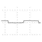
 Stepped/Stair Shaped Encoder Pulses
Stepped pulses occur when two channels are shorted. The shape of the stair can determine which channels are shorted. Learn how to troubleshoot here
 Very Low Amplitude Signals
Low amplitude signals may resemble other channels at a lower amplitude and are generally caused by cross talk to a channel that is actually open. Learn how to troubleshoot here
.jpg?width=170&height=170&name=encoder-output-signal-distortion-example(1).jpg) Delayed Signal Rise Time (Shark Fins)
Delayed Signal Rise Time (Shark Fins)
Shark fin shaped pulses are delays in encoder signal rise time caused by longer cable runs or output driver issues. Learn how to troubleshoot here
 Encoder Signal Flicker/Jump
Encoder signal flickers are erratic jumps in encoder pulse shapes typically resulting from signal interpolation. Learn how to troubleshoot here
Still struggling with Encoder Troubleshooting?

Learn how to troubleshoot with the new HS35IQ with PulseIQTM Technology. This hollow-shaft encoder can connect to a PLC device, stopping guesswork in its tracks. To help you understand just how easy it can be, our expert engineers have created a short video. Here, you will learn about the fault monitoring capabilities of the HS35iQ in a digestible video format.

Looking for a Custom Solution?
Tell us your requirements and our application engineers will help find the right solution today.
Contact Us →
 {{else if (myEq content.heading "Absolute Encoders")}}
 {{/if}}