Encoder Interface Protocols
The output of an incremental encoder is a stream of pulses on one or more channels, while the output of an absolute encoder is a multi-bit word. Encoder interface protocols provide a common language for the encoder and control system to interpret the multi-bit word output of an absolute encoder for information including discrete position, speed and more. Common encoder interface protocols for absolute encoders include parallel, serial, fieldbus, and Ethernet options.
Parallel Encoder Output
The classical approach to interfacing an absolute encoder is through parallel wiring. This scheme requires at least one twisted-pair per bit (data high and data low), plus VCC and ground. The advantage is that all bits are transferred simultaneously, minimizing latency. The drawback is that the increased wire count adds cost, complexity, opportunity for error, and additional points of failure.
It may be provided as straight binary or transformed into gray code. Gray code produces only a single-bit change at each step, which can reduce errors. Learn more about gray code encoders here
Serial Output / Point to Point Encoder Protocols
Serial interfaces provide a simpler, faster, more robust method for transmitting data from the encoder to the controller/counter. The key advantage over traditional parallel wiring schemes is that they aggregate data to minimize wiring. Instead of requiring one twisted-pair (data high, data low) per bit, a serial interface uses a single twisted-pair to send data from all bits in series, reducing wire count compared to parallel output.
A serial interface connects one slave device to one master device. As such, it’s considered a point-to-point wiring scheme. In a point-to-point wiring scheme, the clock remains high until the master needs information from the sensor. When the master polls the encoder, the encoder returns a stream of clock pulses equivalent to the information received from the sensor.
Several different serial interfaces have been established. Some, such as Serial Synchronous Interface (SSI) and Bidirectional Synchronous Serial Interface (BiSS) are open source while others are proprietary.
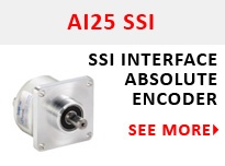
SSI Encoder Protocol: SSI encoders offer an all-digital point-to-point encoder interface with speeds up to 1.5 MHz, depending on cable length. Output options include SSI binary, SSI gray, SSI extended and SSI with Sin-Cos 1Vpp for real time control. Learn more about SSI encoders here
BiSS Encoder Protocol: BiSS is an open source point-to-point encoder interface. BiSS encoders can send full absolute position data whenever the controller polls the encoder, not just at startup allowing for real time control without additional Sin/Cos 1Vpp output. Learn more about BiSS encoders here
When used with a sin-cos signal, a serial interface can provide very high-speed data transfer for real time control. Serial interfaces also significantly reduce wiring compared to parallel wiring. On the downside, they can only connect one slave and one master. They are not good solutions for complex, multi-axis machines that may link dozens of encoders, or axes that may involve encoders on both the motor shaft and the load. For these types of systems, a bus architecture will be more effective.
Popular Serial Output Encoders:
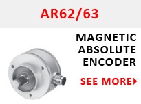
Field Bus Encoder Interfaces
Fieldbus protocols remove the limitations of point-to-point protocols by enabling a single controller (master) to communicate simultaneously with many analog and digital devices (slaves). Connecting with any one device in the network enables the user to interface with all of the devices on the network.
Profibus Encoder Interface: Profibus boasts baud rates to 12Mbps with a maximum segment length of 327 ft and features programmable resolution, preset, and direction. Profibus encoders can communicate speed, direction, and on-time diagnostics.
DeviceNet Encoder Interface: Encoders with DeviceNet have programmable scale, direction, and preset with position data. DeviceNet’s basic trunkline-dropline topology provides separate twisted-pair wires for both signal and power distribution, enabling 24 VDC encoders to be powered directly from the bus. The 0 to 8 byte data packet is ideal for low-end devices with small amounts of I/O that must be exchanged frequently.
Interbus Encoder Interface: Designed by Phoenix Contact in the mid 1980s, Interbus is the longest-standing open industrial network. Interbus is divided into two buses. The remote bus is an RS-485 transmission medium with length capabilities up to 13km. The local or peripheral bus enables connection of up to eight Interbus encoders within a 10m range.
CANOpen Encoder Interface: The CAN network (Controller Area Network) was first used in the automotive industry in the 1980s. The current CAN L2 and CANOpen protocols feature baud rates up to 1Mbps. CANOpen has programmable preset and resolution with L2 having programmable direction and limit values. Both protocols offer speed, acceleration, position, and limit data.
For many of industrial bus protocols, the encoder transmits absolute position only when interrogated by the controller. In others, the encoder sends incremental data as it turns, and provides absolute data either on startup or when interrogated. These methods cut down on bus traffic, but also mean that the control system must know enough to demand an absolute position update whenever there’s a momentary glitch. The update may take only a few milliseconds, but it’s a factor to keep in mind when designing a control system
Popular Field Bus Encoders:

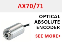

Ethernet Encoder Protocols
Ethernet is an increasingly popular networking approach for industrial automation. Ethernet enables multiple devices to connect across networks of varying topologies. As with fieldbus, connecting with any one device on the network enables a user to access and control any device on the network.
The chief difference between conventional field buses and Ethernet networks is that fieldbus protocols are deterministic, predicated on “best effort” delivery. When data collisions take place, as is a possibility on this kind of network, one transmission will be delayed.
In response to this issue, a number of different industrial Ethernet standards have been developed. Some require ASICS in the equipment while others are purely software based. When making a decision, it’s important to remember that for many applications the level of latency delivered even without special provisions is still good enough to serve even fast applications.
EtherCAT Encoder Protocol: The EtherCAT protocol is optimized for cyclic process data with the integration of a chip in each slave device, instead of a TCP/IP stack as with Ethernet. EtherCAT encoders have fast cycle times and are ideal for high end speed and position control applications that require real time data with deterministic response times.
Profinet Encoder Protocol: The next evolution of Profibus, Profinet has become one of the leading one of the leading Ethernet based protocols on the market. Profinet allows devices or modules to be added and swapped on the fly without stopping the entire machine and is ideal for building highly flexible, modular machines.
Popular Ethernet Encoders:
