Other Categories
Optical Rotary Encoders
Magnetic Rotary Encoders
Hollow-Shaft Encoders
Hub-Shaft Encoders
Shaft Encoders
Miniature Encoders
Hazardous Area Encoders
Non Contact Encoders
Bearingless Encoders
Ethernet Protocol Encoders
Service & Support Overview
Product Quicklinks
Competitor Parts List
Discontinued Encoder Guide
Literature Library
RMA Request
Technical Support
Product Manuals & Installation Guides
Knowledge Center
Technology
How to Choose Feedback
Application Examples
Case Studies
Encoder Issues and Troubleshooting
White Paper Downloads
Literature Library
Power Point Downloads
Videos
Featured Links
Motor Encoders
Quadrature Encoders
Optical Encoders
Magnetic Encoders
How to Specify a Resolver
Draw Wire Encoders
Hall Effect Encoders
Encoder Accuracy vs Resolution
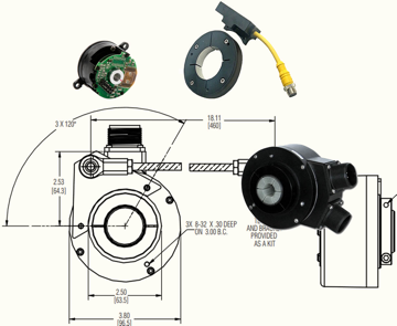
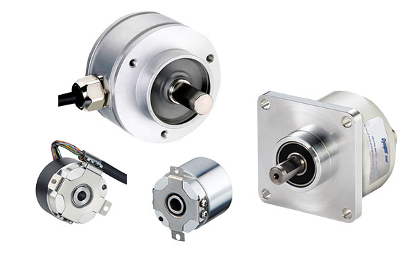
Incremental encoders provide speed, direction and relative position feedback by generating a stream of binary pulses proportional to the rotation of a motor or driven shaft. Dynapar offers both optical and magnetic incremental encoders in 4 mounting options: shafted with coupling, hollow-shaft, hub-shaft or bearingless. Single channel incremental encoders can measure speed which dual channel or quadrature encoders (AB) can interpret direction based on the phase relationship between the 2 channels. Indexed quadrature encoders (ABZ) are also available for homing location are startup.
Select Shaft/Bore Size: Measure your current shaft size to find the best incremental encoder match. Non-matching shafts can be joined with a flexible coupling with mixed bore sizes or by using a shaft adapter.
Select Mounting Style: Shafted incremental encoders are connected by a flexible coupling, belt pulleys, or a drive wheel. They are on a support frame or bracket. Hollow bore encoders slide over and clamp directly onto the drive shaft for space savings. Learn more about mounting methods here.
Select Flange Size (Maximum Housing Diameter): Note the amount of available space to fit the encoder. Use flange size to narrow select by the maximum outside diameter of the encoder body, exclusive of connectors or terminal blocks.
Choose Connection Type: Select from a range of available standard incremental encoder connections, including MS, M12, or Latching Connectors, to match current mating connectors. See a visual guide to common connection types here.
How can we help you?
Contact Support
Compatible Accessories
An incremental encoder is used to identify speed and direction. Operators use incremental encoders for closed loop speed feedback applications where precise coordination between motion devices is required.
There are optical and magnetic type incremental encoders. Both types consist of a spindle assembly, sensor, and cover. As the spindle assembly rotates, the sensor detects motion and translates mechanical motion into electronic pulses. The pulses can then be processed by a controlling device for the purpose of determining speed, direction and relative position.
Learn more about the technology of incremental encoders here
The major difference between an incremental and absolute encoder is that an incremental encoder only provides relative position data to an index location while an absolute encoder provides unique position data without the need to home. Therefore, absolute encoders work in situations where homing at startup is not an option or where immediate operation after power failure is a priority.
© Copyright Dynapar 2025 All Rights Reserved