- Industrial Encoder
- Motor Encoders
- Resolvers
- Incremental Encoders
- Absolute Rotary Encoders
- Magnetic Encoders
- Optical Shaft Encoders
- Optical Rotary Encoders
- Hollow-Shaft Encoders
- Quadrature Encoders
- Draw Wire Encoders
- Hall-Effect Encoders
- Hazardous Location Encoders
- Functional Safety Encoders
- Encoder Interface Protocols
- BiSS Encoders
- SSI Encoders
- Gray Code Encoders
- What is an Encoder?
- Electric Motor Controllers
- Types of Safety Encoders
How to Synchronize Motors with Encoder Feedback
Many applications require the synchronization of two or more motors, including gantries, printing lines, cranes, and conveyor systems. Effectively synchronizing motors requires encoder feedback on each motor.
Encoder Essentials White Paper
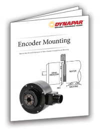
Encoder Mounting. How to Optimize the Life and Performance of Rotary Encoders

Encoder Essentials White Paper
Encoder Mounting. How to Optimize the Life and Performance of Rotary Encoders

There are three types of motor synchronization:
- Velocity Matching
- Angle matching
- Torque matching
Motor Synchronization Methods
There are three major approaches to synchronizing a pair of motors:
Synchronize 2 Motors with A Single Drive
Drives are available that are designed to power multiple motors. Each motor is equipped with its own encoder. The multi-axis drive incorporates multiple I/O boards to accept feedback from each motor. Algorithms within the drive apply feedback to drive the differential to zero.
Although this technique can be used successfully with very closely matched motors, it is generally not the most effective approach. Multi-axis drives typically consist of a power bridge for each axis, managed by a power controller. This design is analogous to putting multiple drives into a single package, with the same issues of power consumption and thermal management. At the same time, it lacks the flexibility and levels of control that would be provided by standalone drives. Discrete drives are more effective.
Synchronize Motors via Master-Slave Architecture
Today’s smart drives feature the processing power and memory required to not just provide commutation commands to the motor but to act as controllers in their own right. When connected in a master-slave architecture, these drives can close velocity and position loops, making them suitable for synchronization.
Master-slave architectures require bidirectional or ring-based network topologies that communicate over digital buses with short cycle times and minimal latencies. The specifics vary from protocol to protocol. In an EtherCAT system, for example, the drive on the master axis sends a telegram to the slave drive, providing it with a motion command and interrogating it for encoder feedback. In the event of a slip or change in one motor, the encoder provides feedback, allowing the system to compensate and maintain the desired speed or position.
Use One Drive per Motor, with PID Loop Control
PID control can be used to synchronize two motors in velocity/position. Each drive commands its respective motor to the same velocity/position, then uses encoder feedback to drive the differential velocity to zero. PID control is most effective when used for position matching; when it’s used for velocity matching, cumulative error can be problematic, depending on the application.
Motor Synchronization in Action
Velocity Matching
Applications for velocity matching include web processing. To avoid jams and damage to the web, the web must always be pulled; the wind axis needs to turn a fractional amount faster than the follower axes. This type of synchronization is best suited to the master slave architecture. The wind axis is the designated master axis. It uses feedback from the slave axes to drive them fractionally slower than the master axis speed.
Another common example is a discharge conveyor that needs to be matched to the speed of upstream equipment. One of the trade-offs of velocity synchronization is that position control is reduced. This typically does not pose a problem for the types of applications discussed, however.
Angle Matching
Press applications require careful synchronization between parts and equipment. A good example of an angle-matching application is a servo press transfer application that requires synchronization of three servo axes with the press position. PID control provides an effective solution for angle matching. The task could also be performed with a master-slave architecture.
The trade-off to angle matching is a reduced control over relative speed.
Torque Matching
Torque matching does not refer to ensuring that both motors generate the same amount of torque. Rather, it involves ensuring that torque from both motors is applied to the load at the same time. Consider a section of aircraft fuselage being lifted by a crane at either end. In order to keep the part level, the motors running the two cranes must start at the same time and run for an identical number of counts. Any differential between them could damage the part or cause injury.
How to Select an Encoder for Motor Synchronization?
The correct choice of encoder begins with understanding the application. What are the requirements for resolution and repeatability? Perfect synchronization is impossible, so determine what the application can tolerate.
It is worth noting here that choosing the highest resolution encoder won’t necessarily drive down error. The role of the encoder in the system is to provide feedback. It falls to the control loop to apply that feedback to drive down error. Its ability to do so is limited by the compliance of the system, however. Installing an ultra-high-resolution encoder on an axis with a significant amount of compliance may just result in an axis that continually overshoots its commanded position, extending settling times. Meanwhile, the choice increases component cost and decreases lifetime and reliability. So, paradoxically, choosing a lower resolution encoder may actually result in a piece of equipment with better performance and improved lifetime.
Learn how to calculate the right encoder resolution for your application here
Looking for a Custom Solution?
Tell us your requirements and our application engineers will help find the right solution today.
Contact Us →

 {{else if (myEq content.heading "Absolute Encoders")}}
 {{/if}}