How to Measure Depth with Rotary Encoders
Delivering a constant stream of depth measurement data in high-risk or hazardous environments can be very challenging. Important characteristics, such as hole depth, are often measured with an encoder. In this article, we will dive into the three methods of depth measurement by encoders, including:
- Measuring rotation of a spinning drum or reel directly at the point of rotation
- Measuring rotation of a spinning drum or reel via pulleys or gear sets
- Measuring depth with a draw wire running parallel to the load
Measuring Rotation of a Spinning Drum or Reel Directly at the Point of Rotation
![measure-depth-with-encoders-diagram1]()
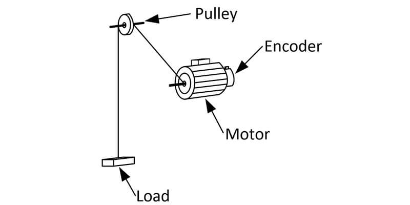
Rotary encoders allow you to measure the depth of a hole by measuring a spinning drum's rotation or reel directly at the rotation point. Often, rotary feedback encoders monitor two critical data points in depth measurement applications. Rotary encoders track drill speed, along with measuring how far the block moves down the hole.
In DrawWorks applications, rotary encoders track a pipe's length by measuring how far the traveling block has moved down the hole. In oil drilling operations rotary encoders are used in the top drives motor gearbox to provide precision feedback, allowing the drive to balance speed in aggregate with the torque applied adequately. Encoders in these applications must have a small form factor, proper specifications, and adequate hazardous location certifications to endure the high temperature, shock, and vibration. Learn more about hazardous rated encoders here

Measuring Rotation of a Spinning Drum or Reel via Pulleys or Gear Sets
![measure-depth-with-encoders-diagram2]()
Depth is an important parameter to measure on a coiled tubing unit. In this application, a friction, or counting wheel, runs along the tubing surface as the CT runs in/ out of the hole. Usually, a chain and sprocket mechanism attached to this friction wheel is used to rotate an encoder's shaft. For every turn of the friction wheel, the encoder turns a specified number of turns.
To calculate the measured depth from the pulses counted by the encoder the following are required: The circumference of the friction wheel, the gear ratio of the chain and sprocket arrangement, and the number of pulses per rotation of the encoder. Measurement of depth and CT speed and its associated calculations is done automatically by most modern data acquisition systems.
Typically, measuring heads will use spring loaded measuring wheels to measure the amount of wire line moving from the bore hole. Each measuring wheel is coupled to one or two optical encoders that send data to the logging computer which communicates.
Measuring Depth with a Draw Wire Running Parallel to the Load
![measure-depth-with-encoders-diagram3]()
Encoder feedback is critical to track and monitor routine maintenance and operating conditions. For instance, as you dig deeper into the layers of Earth, the pressure and temperature can change. Encoders provide useful measurements that indicate the health of a drill bit, how much windup to expect, and how to properly weight the drill string.
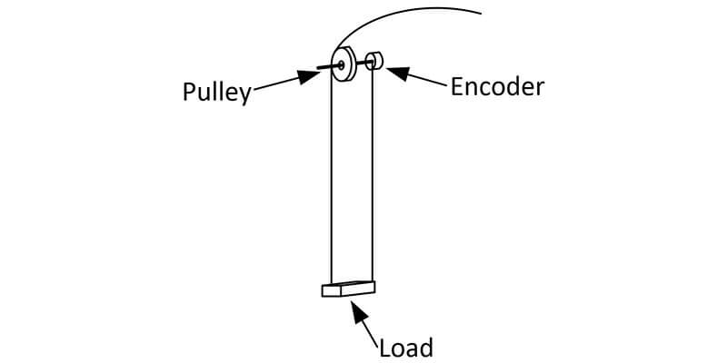
Draw wire encoders are ideal for applications where there is a high degree of risk of the point of rotation slipping or not accurately tracking the load. In the method above, pulley wheels may wear over time, especially in rugged environments, causing potential changes to the diameter of the wheel. Therefore, draw wires encoders are better suited for heavy duty environments. Learn more about how to measure distance with draw wire encoders here
Related Articles
Demystifying Encoder Resolution, Encoder Accuracy and System Repeatability
Critical Considerations when Specifying for Encoder Shock and Vibration
Encoder Wiring Best Practices


