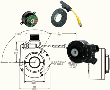
Size 10 Motor Resolver
Size 10 brushless resolver, super compact size, bore sizes of 4mm, 6mm or 1/4" and single speed accuracy of 15 arcmin max
Learn More

A resolver consists of a primary winding and a pair of secondary windings, each with a sinusoidally varying winding density. The primary winding rotates with the load. The secondary windings, known as the sine and cosine windings, are fixed in position with a 90° offset from one another; hence the names.
Encoders or Resolvers? How to Choose the Right Feedback Option
A resolver outputs an analog signal caused by current passing to the primary winding which generates a magnetic field. When the winding turns with the load, it excites separate output voltages in the sine winding and the cosine winding. The ratio of these two voltages can be processed to calculate the angular position of the load.
The key electrical characteristics for a resolver are:
 Input excitation voltage and frequency refer to the input AC voltage (Vrms) and frequency supplied to the leads of the primary winding by the system. These voltages typically range from 1 to 26 VAC, at a frequency of 400 to 10,000 Hz. A given winding can operate over a range of voltages and frequencies without significant change in performance. Large departures from the rated voltages and frequencies can introduce electrical errors and low-voltage outputs, however. For accurate results, it is essential to properly size the resolver for the application.
The maximum input current is the current in amps that is required to energize the primary winding at the system input voltage and frequency. Per Ohm’s Law, current is proportional to the ratio of input voltage to winding resistance (I = V/R). For a given resolver winding and input voltage, the resolver will draw a specified current. This current will vary slightly depending on small variations in wire diameter, and on changes to drive voltage. This is why datasheets specify a maximum input current for a given resolver part number.
It may be more instructive to think in terms of power, which is given by P = IV=I2R. A resolver requires a resolver interface card (or functionality) that is located in the drive. The interface card includes the electronics to perform two functions:
Separating the electronics from the resolver itself enables resolvers to survive harsh operating conditions such as extreme temperatures, voltages, currents, and radiation levels. Each interface card has a maximum power capability; it is essential to choose a resolver that is compatible with the parameters of the interface card.
The transformation ratio (TR) of a resolver is the ratio of its output voltage to input voltage when the output voltage is at maximum magnetic coupling. Recall that a resolver is a specialized transformer where the output voltage is a function of the angular position. During operation, it takes the input voltage and normally steps it down to an output voltage (sometimes it steps it up, and sometimes the TR is unity). The TR is a useful metric for determining whether a resolver will operate appropriately in a system.
Winding design determines the TR of a resolver; roughly speaking, TR is the ratio of the number of turns in the secondary winding to the number of turns in the primary winding. As a result, a manufacturer can customize resolver windings to produce TR required for the system without significantly affecting performance.
If the system shows a warning light or alert for the resolver, the problem could be the resolver output voltage. As noted above, the resolver interface card both supplies voltage to the resolver and receives the output signal from the resolver. Interface cards are set to deliver a specific input voltage to the resolver but they also may be programmed to look for a minimum output voltage from the resolver. If the output voltage falls below that level, it may trigger a warning light. The alert does not necessarily mean there is a problem with the resolver, but it does need to be investigated.
Troubleshooting steps include:
Remember that the cause may be a combination of two or more of the root causes listed above. Be sure to check for all three before concluding troubleshooting.
For a final troubleshooting tip, remember that a resolver is essentially a specialty transformer. If it fails, it will fail either as a short-circuit or an open circuit. If you test your system and find either condition, the next step needs to be isolating the location of that short or open circuit. Although resolvers have been known to fail, it is rare that this occurs after they leave the factory. Before you box up the component and send it back, be sure that the problem is in the resolver and not elsewhere in the system.
Resolvers do not require any onboard electronics; as a result, they can tolerate very harsh conditions such as temperature extremes, contamination, high radiation, and shock and vibration. However, resolvers should be specified with care. To optimize your results, work closely with your vendor to ensure that you choose the appropriate device for your application.
Learn more about resolver technology here
Learn how to specify resolver speed and accuracy here
Download our white paper on the key differences between encoders and resolvers here
Download our white paper on how to specify the best resolver for your application here
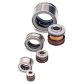
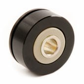
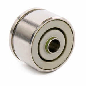
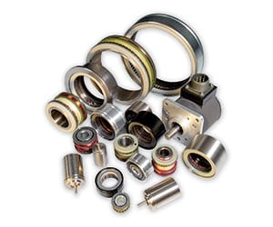
Dynapar offers frameless resolver and housed resolver options. Frameless resolvers with rotor and stator assemblies that can be housed in servo motors, direct drive motors, rotary platforms and more to provide motion feedback. Housed resolvers provide reliable feedback in a sealed package with various IP rated models. See our most popular resolver models: