A position sensor is a device that measures linear or angular position. Common tradeoffs include resolution, robustness, lifetime and cost. The most widely used position sensors for industrial applications are:
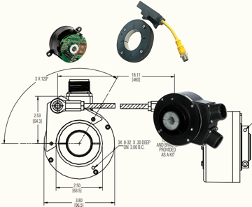
Encoders are rotary and linear feedback devices that can be used as position sensors. Encoders calculate the position, speed, and direction of another device. Incremental encoders generate a pulse stream corresponding to displacement from a home position established at startup. Absolute encoders read out a multi-bit digital word corresponding to absolute position.
Encoders are available with both optical encoder and magnetic encoder sensing engines. Optical encoders provide the highest resolution and accuracy, but they are vulnerable to contamination. Magnetic encoders can survive very harsh environments but their resolution is limited. Typical magnetic encoders use Hall-effect sensor chips to generate an absolute signal. This enables them to deliver accurate performance even in applications involving high shock and vibration.
Depending on the application, the devices can be configured to measure angles within ±360° (single-turn designs) or rotations in excess of ±360° (multi-turn designs).
Inclinometers
Monitoring the angle of incline is important in applications as varied as off-road vehicles and scissor lifts. Inclinometers provide a solution. The traditional versions are based on small pendulums. More recently, the industry has moved toward solid-state designs that incorporate micro-electromechanical systems (MEMS) accelerometers
The accelerometer consists of a small wafer-like test mass suspended from a fixed frame by flexures. An electrode projects from each side of the test mass to the space between a corresponding pair of fixed electrodes that project out from the frame. Tilting the inclinometer causes the test mass to move. This alters the spacing between the test-mass electrodes and the frame electrodes, which modifies the capacitance. That data can be processed to yield angle.
Because they are solid state devices, inclinometers are robust and economical. They are also well sealed and easy to mount.
As always, there are drawbacks. The devices can be sensitive to shock and vibration. For static applications, this can be physically damped or removed with software filters. For dynamic applications, the MEMS accelerometer needs to be combined with a MEMS-based 3-D gyroscope.
Perhaps a bigger problem is that at its heart, this represents an indirect measurement. The data from the accelerometer needs to be processed to yield an angle, which can introduce a delay. A direct-read rotary device like a Hall-effect sensor or an encoder gives faster results and a more accurate reading.
Laser-based position Sensors
The simplest type of laser position sensor is a time-of-flight laser rangefinder. These systems measure distance by monitoring the amount of time required for an optical pulse to travel from the laser to the target and back to a detector. They are fast, repeatable, and offer spatial resolutions of a few millimeters.
They are sensitive to alignment errors, particularly when a retro reflector must be used on a target that otherwise has a diffuse surface. They are very sensitive to environmental conditions. Heat, humidity, contamination, and vibration degrade laser performance. Humidity and particulate matter can contaminate the retro reflector and prevent it from producing a specular reflection to return to the detector. Dust and humidity in the optical path traveled by the beam can scatter the light and lower the signal-to-noise ratio.
For applications with higher performance demands, laser interferometers deliver resolutions on the order of a wavelength of light. These devices measure distance based on the interference between a test beam and a reference beam. They are both accurate and repeatable. On the downside, they suffer from all the problems of a laser rangefinder but to a greater degree. They are also much more expensive. For a demanding application in a clean, controlled environment, however, they can work well.
Potentiometers
A potentiometer is an adjustable voltage divider that is based on a three-terminal resistor. One terminal is connected to a voltage source while another is connected to ground. The third terminal connects to a brush that slides along a fixed resistive surface. For potentiometers used as position sensors, the brush is attached to the load. When the load moves, the brush slides over the resistive surface. This alters the resistance, causing a change in output voltage.
Potentiometer-based position sensors can be configured as rotary or linear designs. In a rotary version, the resistive surface is a ring while in the linear version, it is a straight track. Potentiometers are inherently absolute position sensors, needing no rehoming after an outage. Because of the operating mechanism, the resolution of a potentiometer is theoretically infinite; practically speaking, it is limited by the performance of the readout electronics. These devices are; economical and familiar to most engineers and maintenance technicians.
On the downside, potentiometers are based on sliding physical contact, so their lifetime is limited. They are also vulnerable to contamination. Output linearity varies depending on the parameters of the device and the interaction between the brushes and the resistive surface. Potentiometer-based position sensors are designed for a limited number of turns. This limits their ability to track a load and should be taken into account when specifying.
Proximity sensors
As its name suggests, a proximity sensor uses any of several sensor technologies to detect when an object is nearby. The simplest proximity sensors are just switches. More sophisticated versions provide gradient feedback depending upon proximity. They can be implemented using a variety of technologies including:
Photoelectric (both IR and visible signals)
Inductive
Ultrasonic
They can be used for positioning by installing them at each key point of the system to send a signal when triggered by some target on the load. For a rotary indexing table, for example, a switch could be installed at 0°, 90°, 180°, and 270°. It’s an economical and effective approach for applications requiring limited feedback but quickly becomes impractical for any kind of high-resolution positioning.
Dynapar offers non-contact sensors that come in proximity sensor sizes, while offering high resolution incremental and absolute feedback:
Resolvers
For applications subject to ultra-harsh conditions like extreme temperatures, high shock and vibration, and contamination, resolvers may provide the best angular feedback solution. A resolver is a specialized type of transformer that operates without onboard electronics. The device consists of two fixed primary (excitation) windings and two rotating secondary (signal) windings attached to the load. Running a voltage through the excitation windings induces a voltage in the signal windings. The magnitude of the voltage varies depending upon the angle of the load. Taking the arctangent of the ratio of the appropriate coil voltage returns the angle within one full rotation of the load.
Because the results are based upon a ratio of analog electrical signals, resolvers offer infinite theoretical resolution. As with potentiometers, however, the practical resolution of the system is limited by the off-board processing electronics.
Resolvers can be purchased as both housed and frameless designs. This makes them highly adaptable. Their performance is dependent on alignment, however, which means that some expertise is required to achieve best results.
Ultrasonic Sensors
Ultrasonic position sensors also operate on the time-of-flight principle, using piezoelectric or electrostatic elements to generate ultrasonic signals. They are effective over distances of up to about 10 m, although accuracy falls off with distance. They have a blind zone of a few centimeters at the sensor face.
Ultrasonic sensors are robust with regard to shock, vibration, and contamination. They are insensitive to variations in color and temperature of the object under test. Because the calculations are based on the speed of sound, however, they have some weaknesses. They are not effective on soft, sound-absorbing materials. They are sensitive to variations in temperature, humidity, and altitude that could alter the way acoustic waves propagate in air. Some systems apply compensation factors but highly dynamic environments may need special provisions.
Commercial versions of ultrasonic sensors are available. As with laser-based systems, there is a learning curve. Integrating them into the system and interpreting the results tend to be the most challenging aspect of using the technology.
Ultimately, the choice of technology should be driven by the application. What is the user trying to do? What information do they need from the device? What are the conditions? And, of course, what does the budget cover? It’s also important to consider the skill sets of the staff who will be installing, operating, and maintaining this equipment.

 Encoders