Other Categories
Optical Rotary Encoders
Magnetic Rotary Encoders
Hollow-Shaft Encoders
Hub-Shaft Encoders
Shaft Encoders
Miniature Encoders
Hazardous Area Encoders
Non Contact Encoders
Bearingless Encoders
Ethernet Protocol Encoders
Service & Support Overview
Product Quicklinks
Competitor Parts List
Discontinued Encoder Guide
Literature Library
RMA Request
Technical Support
Product Manuals & Installation Guides
Knowledge Center
Technology
How to Choose Feedback
Application Examples
Case Studies
Encoder Issues and Troubleshooting
White Paper Downloads
Literature Library
Power Point Downloads
Videos
Featured Links
Motor Encoders
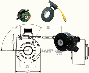
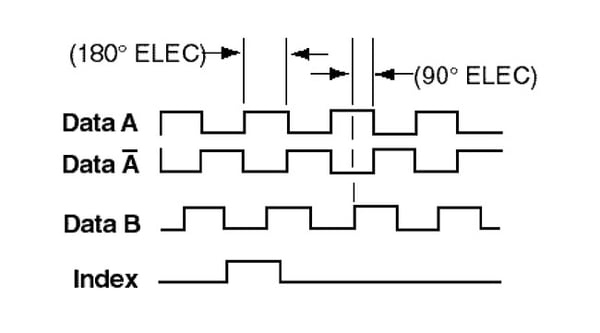
Quadrature Encoders
Optical Encoders
Magnetic Encoders
How to Specify a Resolver
Draw Wire Encoders
Hall Effect Encoders
Encoder Accuracy vs Resolution


.jpg?width=170&height=170&name=encoder-output-signal-distortion-example(1).jpg)